Corrosive environment sensor and method for measuring corrosive environment

A technology of corrosive environment and measurement method, which is applied in the field of corrosive environment sensor and corrosive environment measurement, and can solve problems such as inability to be completely consistent.

Inactive Publication Date: 2012-10-17
SUZUKI MOTOR CORP
View PDF3 Cites 6 Cited by
  • Summary
  • Abstract
  • Description
  • Claims
  • Application Information

AI Technical Summary

Problems solved by technology

Therefore, the corrosion environment formed in the simulation space of the corrosion environment sensor cannot completely match the actual corrosion environment in the overlapping parts.

Method used


Image

  • Corrosive environment sensor and method for measuring corrosive environment
  • Corrosive environment sensor and method for measuring corrosive environment
  • Corrosive environment sensor and method for measuring corrosive environment

Examples


Embodiment Construction

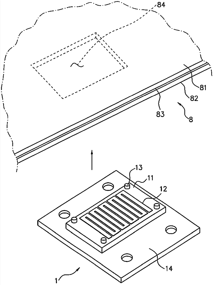
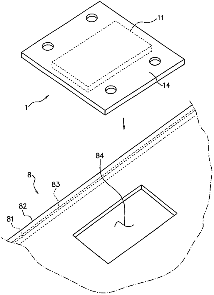
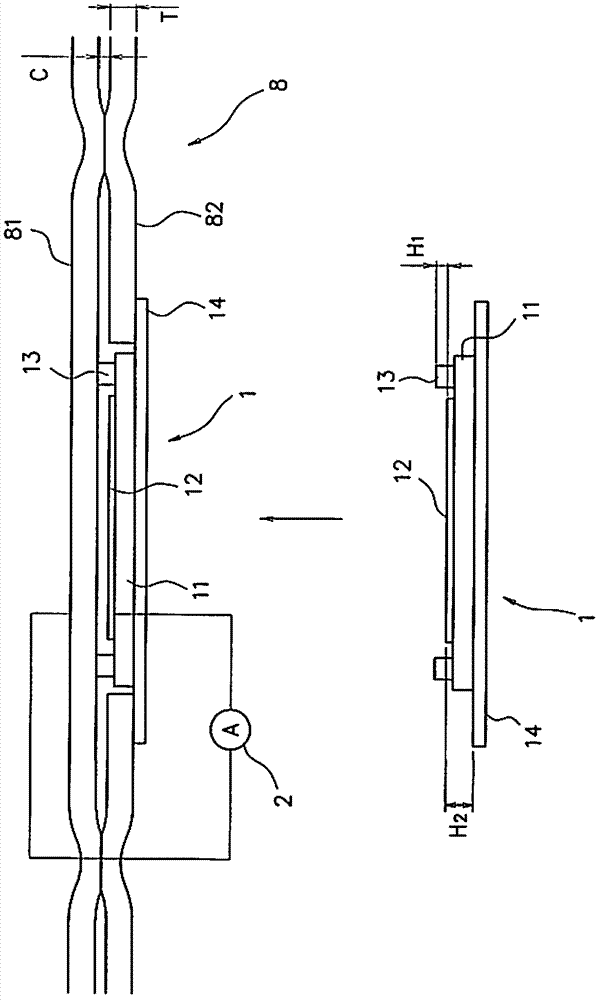
[0027] Hereinafter, embodiments of the present invention will be described in detail with reference to the drawings. The corrosion environment sensor 1 according to the embodiment of the present invention can measure the corrosion environment of a gap between two members in which at least one member is a conductor. Among them, the “corrosive environment” is defined as the influence of the environment on the corrosion of structures and the like (corrosiveness of the environment). In the following description, as the measurement target, the structure 8 having the overlapping portion where the first member 81 and the second member 82 overlap is shown as an example. In addition, Figure 1 ~ Figure 3 The overlapping portion where the first member 81 and the second member 82 overlap are extracted and shown. In addition, the first member 81 is a conductor. For the first member 81, when there is no conductivity, scrape off the insulator layer, film (for example, paint, oxide film), ...


PUM


Abstract

The invention provides a corrosive environment sensor and a method for measuring a corrosive environment. The corrosive environment sensor for measuring corrosive environment inside a space between a first member that is a conductor and a second member that is a conductor or insulator includes: a base having a surface which cam face the first member that is a conductor; and an electrode which is provided on the surface of the base and formed with a material different in ionization tendency from the first member and which faces at a distance the first member so as to form a galvanic coupling with the first member, and the corrosive environment sensor measures a galvanic current between the electrode and the first member.

Description

Technical field [0001] The invention relates to a corrosion environment sensor and a corrosion environment measurement method. In detail, the present invention relates to an ideal corrosion environment sensor for measuring the corrosion environment inside a gap existing in a structure, and corrosion environment measurement using the corrosion environment sensor to measure the corrosion environment inside a gap existing in the structure method. In addition, the “corrosive environment” is defined as the influence of the environment on the corrosion of structures and the like (that is, the corrosiveness of the environment). Background technique [0002] In a structure composed of a combination of metal members, there may be gaps in portions where the metal members overlap each other. For example, in a structure where the overlapping parts of metal members are spot welded, the metal members may not be completely in close contact with each other, and a gap may occur. It has gradual...

Claims


Application Information

Patent Timeline
Patent Type & Authority Applications(China)
IPC IPC(8): G01N17/04
CPCG01N17/043
Inventor 仲田琉璃小长井信寿﨏孝太伊藤裕也
Owner SUZUKI MOTOR CORP
Why Eureka
Try Eureka