
Novel bridge inspection vehicle

A bridge maintenance vehicle, a new type of technology, applied in the direction of bridge maintenance, bridges, bridge parts, etc., can solve problems such as limited, large cantilever on both sides, complicated locks, etc.

Inactive Publication Date: 2012-10-17
CHINA MAJOR BRIDGE ENERGINEERING
View PDF7 Cites 17 Cited by
  • Summary
  • Abstract
  • Description
  • Claims
  • Application Information

AI Technical Summary

Problems solved by technology

When the transverse width of the bridge is greater than the longitudinal obstacle, the maintenance work on the outer side of the truss must be completed, and the vehicle body cannot be rotated.
In addition, the car body and the walking part are separated and connected by a turntable. The structure is complex, the cantilever on both sides is large, and the structure is not stable enough when working
[0004] Afterwards, there is an overhaul vehicle in which the car body and the cantilever additional car body on both sides are connected by telescopic sockets. Length and socket joints, so the length of the socketed car body on both sides does not exceed one-half of the body, so the total length after stretching is less than twice that of the car body, and the working surface widened to both sides of the track is very limited
[0005] Therefore, in the past, there was often no inspection vehicle inside the truss, and the inspection and maintenance work was often completed by workers setting up temporary scaffolding.

Method used


Image

  • Novel bridge inspection vehicle
  • Novel bridge inspection vehicle
  • Novel bridge inspection vehicle

Examples


Embodiment Construction

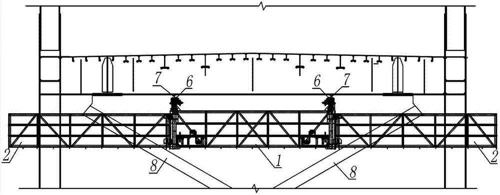
[0018] The vehicle body of the present invention is composed of a vehicle body 1 in the middle and cantilever additional vehicle bodies 2 on both sides, and is connected as a whole by a rotary hinge 3 and a fixed pin 4 . The top of the car body 1 is equipped with a wheel mechanism 6, suspended under the longitudinal track 7 of the bridge, and the opening and closing handle 5 is installed at the front or rear end of the rotating hinge 3 on both sides, and the other end is provided with a fixed pin jack 4, and the two sides are connected to each other. relative to the direction.

[0019] The present invention usually takes the form of figure 1 , 2 , The expansion mode shown in 3 walks longitudinally along the bridge. When encountering the horizontal connecting member 8 in the truss, turn the opening and closing handle 5, and the cantilever additional car body 2 on both sides will rotate horizontally through the rotating hinge 3 and overlap the front and rear of the car body, s...


PUM


Abstract

The invention relates to a novel bridge inspection vehicle, which is a travelling crane applied to inspection of the inner side or bottom of a truss bridge in a manner of a rotary folding vehicle body. The inspection vehicle body is composed of a middle vehicle body and additional vehicle bodies on cantilevers at two sides together, wherein the vehicle body and the additional vehicle bodies are mutually connected through a rotating hinge and a fixing pin, and a wheel mechanism is arranged above the vehicle body. The inspection vehicle walks and works under the track on which the bridge is vertically arranged in an unfolding manner in general; a hand shank is rotationally opened and closed when the inspection vehicle comes across a lateral coupling system member in a truss or a pier support; and the additional vehicle bodies on the cantilevers at two sides horizontally rotate oppositely, and are overlapped on the front and back parts of the vehicle body, and the vehicle body is folded and shortened into 1 / 3 of original length and then traverses an obstacle. According to the invention, an inspection work surface is expanded and the inspection vehicle can extend to the outer side of the truss to work. The distance between the tracks is wide, and the vehicle body and the tracks are directly connected by the wheels, so the inspection vehicle is stable in structure when walking and working. The novel bridge inspection vehicle has the advantages of being simple in structure, convenient to use, economic and practical, and has been successfully applied to engineering practice.

Description

technical field [0001] The invention relates to a novel bridge maintenance vehicle. Background technique [0002] To ensure the safe use of bridges, maintenance work is essential. This maintenance vehicle is used for the maintenance of the inner side or bottom of the truss bridge. In order to meet the inspection and maintenance work, the truss of the vehicle body must have a relatively long length. When the maintenance vehicle travels along the longitudinal track of the bridge, the maintenance vehicle cannot directly pass through because there are many horizontal connecting members in the truss or the supports of the bridge span. . [0003] There was once a kind of overhaul vehicle whose body length was fixed and rotated as a whole. The car body and the walking part were connected by a turntable. Now with the development of traffic, bridges are built wider and wider, but the vertical spacing of horizontal connections is limited. When the transverse width of the bridge is...

Claims


Application Information

Patent Timeline
IPC IPC(8): E01D19/10E01D22/00
Inventor 刘承虞高宗余易伦雄肖海珠张成东胡辉跃
Owner CHINA MAJOR BRIDGE ENERGINEERING
Learn More