
Tyre packing machine and packing method

A packaging machine and tire technology, applied in packaging, wrapping paper, transportation packaging, etc., can solve the problems of easy damage, slow packaging, and high packaging costs, improve tightness and firmness, reduce the possibility of damage, and improve packaging. low cost effect

Inactive Publication Date: 2012-10-17
青岛科力达机械制造有限公司
View PDF6 Cites 9 Cited by
  • Summary
  • Abstract
  • Description
  • Claims
  • Application Information

AI Technical Summary

Problems solved by technology

[0002] The existing packaging methods for tires are all winding, that is, using strip-shaped packaging materials, and using a tire winding machine to wrap the strip-shaped packaging materials on the tire with overlapping edges. Large amount of materials, high packaging cost, serious waste of packaging materials, easy to loose after packaging, poor stability, slow packaging speed, low packaging productivity
[0003] The previous patent "Tire Packaging Machine" (Patent No. ZL99117123.3) designed a tire packaging equipment, using a non-winding packaging method, but there are still many defects. The packaging method is the packaging method of pressing the upper mold and the lower mold. When packing, the tire needs to be positioned accurately, the position is high, the packaging process is high, and the length of the connection is long. The connection of the outer ring of the upper mold and the lower mold is located on the tire tread for one week, completely exposed on the outside, and it is easy to Damage occurs, the stability is weak, and the packaging effect is not beautiful, the outer ring is bonded as a whole, resulting in a lot of packaging waste, low utilization rate of packaging materials, and high packaging cost

Method used


Image

  • Tyre packing machine and packing method
  • Tyre packing machine and packing method
  • Tyre packing machine and packing method

Examples


Embodiment Construction

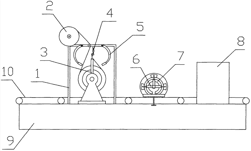
[0029] The tire packaging machine of the present invention, such as figure 1 As shown in the figure, a vertical tire feeding device is included, and a tire tread wrapping device, a tire inner ring bonding device, and a baking tightening device 8 are sequentially installed on the vertical tire feeding device along the tire feeding direction. The tire tread The wrapping device includes a frame 1. The frame 1 is provided with a feeding device 2, a tire wrapping device 3, a tire lifting device 4, and an outer ring bonding device 5. The feeding device 2 is located above the tire wrapping device 3. The tire inner ring The gluing device includes a flanging device 6 and an inner ring gluing device 7 , and the inner ring gluing device 7 is installed on the flanging device 6 .

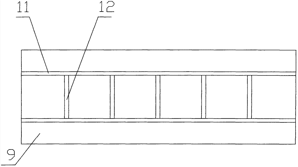
[0030] like figure 2 As shown, the vertical tire feeding device includes a base 9 and a conveying device 10 mounted on the base 9. The conveying device 10 includes two chains 11 parallel to each other, and a p...


PUM


Abstract

The invention discloses a tyre packing machine, which comprises a vertical tyre feeding device. A tyre surface wrapping device, a tyre inner ring bonding device and a baking and tightening device are sequentially arranged on the vertical tyre feeding device along the tyre feeding direction. A tyre lifting device of the tyre packing machine can be used for positioning a tyre, the requirement for the placing position of a material fed by a feeding device is low, the joint of packing tapes on the surface of the tyre is short, and the joint is only positioned at a certain position on the outer periphery of the tyre; the probability of breakage of the tyre in the carrying process is reduced, packing aesthetic feeling is promoted, little packing waste is produced, the utilization rate of a packing material is high, and the packing cost is low; by adjusting the height of the tyre packing device, the tyre packing machine can be used for packing tyres with different sizes and is strong in compatibility; through two heating bonding plates on a tool rest and an annular hot knife in the inner ring bonding device, attractiveness of the bonding surface is ensured; and through the baking and tightening device, the packing tapes are tightly attached to the surface of the tyre, and packing tightness and firmness are improved.

Description

technical field [0001] The invention relates to a packaging machine and a packaging method thereof, in particular to a packaging machine for packaging tires and a tire packaging method using the packaging machine. Background technique [0002] The existing tire packaging methods are all winding types, that is, a belt-shaped packaging material is used, and a tire winding machine is used to wrap the belt-shaped packaging material on the tire with overlapping edges. The material consumption is large, the packaging cost is high, the packaging material is seriously wasted, and it is easy to loosen after packaging, the stability is poor, the packaging speed is slow, and the packaging productivity is low. [0003] The previous patent "Tire Packaging Machine" (Patent No. ZL99117123.3) designed a tire packaging equipment, which uses a non-winding packaging method, but there are still many defects. When packing, the tire needs to be positioned accurately, the location requirements ar...

Claims


Application Information

Patent Timeline
Patent Type & Authority Applications(China)
IPC IPC(8): B65B25/24B65B11/02B65B35/24B65B61/06B65B51/10B65B53/02
Inventor 李卫星孙贤功
Owner 青岛科力达机械制造有限公司
Learn More