
Novel packing machine

A new type of packaging and rack technology, applied in the direction of packaging, transport packaging, multiple packages, etc.

Active Publication Date: 2014-03-26
SHANGHAI SOONTRUE MACHINERY EQUIP
View PDF7 Cites 0 Cited by
  • Summary
  • Abstract
  • Description
  • Claims
  • Application Information

AI Technical Summary

Problems solved by technology

[0008] In order to overcome the above-mentioned defects of the material packaging machine such as slippage, damaged roll film, different sizes of packaging bags, and inability to pack fragile items, the present invention provides a new type of packaging machine , the packaging machine will not produce defects such as slippage and film damage, and the application range of packaging materials is wide, especially suitable for packaging fragile items, and the defective and waste products after packaging are low.

Method used


Image

  • Novel packing machine
  • Novel packing machine
  • Novel packing machine

Examples


Embodiment 1

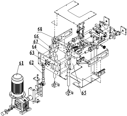
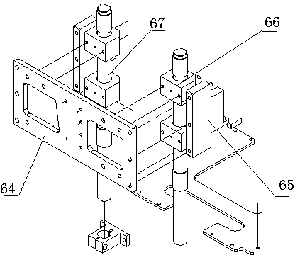
[0033] Such as figure 1 , figure 2 and image 3 As shown, a new type of packaging machine includes a frame 3, a film-moving mechanism 2, a bag-forming mechanism 4, a vertical sealing mechanism 5 and a horizontal sealing mechanism 6. It is characterized in that: according to the direction of film movement, the film-moving mechanism 2 , the bag forming mechanism 4, the longitudinal sealing mechanism 5 and the horizontal sealing mechanism 6 are installed on the frame 3, the bag forming mechanism 4 is installed above the vertical sealing mechanism 5, and the vertical sealing mechanism 5 is installed above the horizontal sealing mechanism 6, The horizontal sealing mechanism 6 includes a horizontal sealing device 68 and a lifting mechanism. The lifting mechanism includes an upper and lower horizontal sealing connecting plate 64, a guide shaft 67 fixed on the upper and lower horizontal sealing connecting plate 64, and a horizontal sealing seat fixed on the guiding shaft 67. Plate...

Embodiment 2

[0035] Such as Figure 4 As shown, the preferred horizontal sealing device 68 of this embodiment on the basis of Embodiment 1 includes a front knife seat fixing seat 685, a rear knife seat fixing seat 6812, and a heat insulation pad 686 arranged between the front and rear knife seat fixing seats. , The front knife seat 684 and the rear knife seat 683 arranged between the heat insulating pads 686, the front knife seat 684, the rear knife seat 683, the front knife seat fixing seat 685, and the rear knife seat fixing seat 6812 pass through the horizontal sealing guide shaft 11 connected, the two sides of the front knife seat fixing seat 685 and the rear knife seat fixing seat 6812 are provided with sliding blocks 6810, the sliding blocks 6810 are connected to the front and rear connecting plates through the pin shaft 687, and the sliding block 6810 is equipped with a linear sliding film , the sliding block 6810 is equipped with a rack fixing plate 682 on the left and right, front...

Embodiment 3

[0037] Such as Figure 4 and Figure 5 As shown, in this embodiment, on the basis of Embodiment 2, the horizontal seal guide shaft 11 is a horizontal seal single guide shaft, and the horizontal seal single guide shaft is provided with a linear sliding bearing 12, which is mainly supported by two sets of upper and lower sliders 13 Fix the linear sliding bearing 12 to make the single horizontal seal guide shaft slide smoothly, and it is mainly used in short tool holders and narrow tool holders, and under light load conditions.


PUM


Abstract

The invention discloses a novel packing machine which comprises a frame, a film delivery mechanism, a bag forming mechanism, a longitudinal seal mechanism and a transverse seal mechanism. According to the movement direction of a film, the film delivery mechanism, the bag forming mechanism, the longitudinal seal mechanism and the transverse seal mechanism are orderly arranged on the frame; the bag forming mechanism is arranged at the upper part of the longitudinal seal mechanism; and the longitudinal seal mechanism is arranged at the upper part of the transverse seal mechanism. The transverse seal mechanism consists of a transverse seal sealing mechanism and a lifting mechanism; and the lifting mechanism comprises an upper transverse seal connecting plate and a lower transverse seal connecting plate, a guide shaft fixed on the upper and lower transverse seal connecting plates, and a base plate fixed on the guide shaft. The guide shaft is provided with a slip line bearing block. The base plate is connected with the transverse seal sealing mechanism. The novel packing machine is used for packing fragile items, and the operation is stable, continuous and efficient.

Description

technical field [0001] The invention relates to a packaging machine suitable for bag making and packaging of fragile items, especially for granular, powdery, solid materials and frozen foods (food such as dumplings). Background technique [0002] The material packaging machine can make heat-sealable flexible materials into pouches, and at the same time automatically pack powder, liquid, colloidal, paste, and solid materials into pouches. The material packaging machine generally includes a feeding mechanism, a film feeding mechanism, a former, a vertical sealing mechanism, and a horizontal sealing mechanism. When in use, the film feeding mechanism continuously sends out the packaging film, and the former guides the packaging film to be stacked into a double-layer structure. The longitudinal sealing machine heat-seals the packaging film in the longitudinal direction. The existing longitudinal sealing mechanism has two pairs of circular wheels, and each pair of circular wheels ...

Claims


Application Information

Patent Timeline
Patent Type & Authority Patents(China)
IPC IPC(8): B65B9/067B65B51/26
Inventor 黄松徐宏佟庭胜郑子农周忠福
Owner SHANGHAI SOONTRUE MACHINERY EQUIP
Learn More