
Packaging machine capable of being applied to sampling industry

A packing machine, sample collection and preparation technology, applied in packaging, transportation and packaging, capping with auxiliary devices, etc., can solve the problems of uneven transportation, failure to seal successfully, high labor intensity, etc., and achieve simplified storage and capping. Cover mechanism, prevent counterfeit and inferior products, and have high operational reliability

Active Publication Date: 2014-12-03
长沙通发高新技术开发有限公司
View PDF7 Cites 0 Cited by
  • Summary
  • Abstract
  • Description
  • Claims
  • Application Information

AI Technical Summary

Problems solved by technology

Based on the needs of users, at present, all domestic sampling and production manufacturers are eager to try and start to try to integrate packaging and coding systems on their own sampling and production equipment. The ready-made balers and inkjet printers produced and sold by manufacturers in the food machinery industry are originally designed for the packaging of the food industry. After being applied to the sample collection industry, due to changes in environmental conditions, It is difficult to use normally, and the failure rate is very high. It is simply not suitable for product packaging in the sample collection industry, and it may even have a negative impact on the stable operation of the entire equipment.
[0004] The plastic film baler has the following disadvantages: ①Due to the relatively low strength of the plastic bag, a sample bag can only hold a few kilograms of samples, so generally it can only be used for packaging samples of 5kg or less; ②The site conditions are harsh, the dust is heavy, and it is easy to The length of the roll bag is wrong, often due to the slipping of the dragging roller, the sample bag is much shorter than the set bag length, and the material cannot be loaded; ③Due to dust, the seal cannot be successfully sealed after the dust is stuck on the heat-sealed part; ④The sensor on the baler There are also many, such as photoelectric sensors for measuring the position of plastic bags, servo controllers, etc., which are prone to false signals in a high-dust environment, causing the equipment to fail to work normally
The plastic film baler integrated with the inkjet printer also has the following disadvantages: ①The inkjet printer has relatively high requirements for the use environment. In terms of ambient temperature, the normal ink ejection cannot be guaranteed if the ambient temperature is lower than 5°C; ②The external dust In a large environment, the nozzles are easily blocked, and the nozzles need to be cleaned manually with alcohol every day, which is cumbersome to operate; ③The inkjet printers spray out numbers or letters, and cannot spray out barcodes and other information that can be automatically recognized by the machine
[0005] The woven bag baler has the following disadvantages: ①It is necessary to manually place the IC card in the woven bag before going to work every day, and put dozens of sample bags into the bag slot, which is relatively labor-intensive; ②The pneumatic suction cup sucks the woven bag There are often cases where the bag cannot be sucked, resulting in the failure of the bag; ③The pneumatic suction cup cannot be sucked when it sucks the woven bag to open the bag mouth, resulting in the bag opening being unable to open; ④When the woven bag is stitched by the sewing machine, the sewing machine ⑤After the woven bag is stitched, the thread cutting fails when the suture thread is automatically cut off, which leads to the failure of the next sample bag to be sewed normally; , making it difficult to maintain the level of the woven bag, causing the suture line to be not straight, which in turn causes part of the woven bag to fail to be sutured, resulting in suture failure
[0006] More importantly, when the aforementioned technical problems occur, the existing balers cannot automatically detect the faults that have occurred in the equipment, nor can they provide an alarm signal to the corresponding controller, resulting in a high scrap rate of samples

Method used


Image

  • Packaging machine capable of being applied to sampling industry
  • Packaging machine capable of being applied to sampling industry
  • Packaging machine capable of being applied to sampling industry

Examples


Embodiment

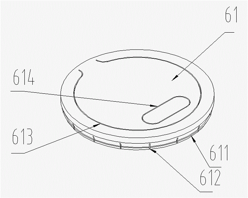
[0044] like Figure 2~Figure 4 As shown, the charging barrel 6 of the present embodiment is cylindrical, and the inner wall of the charging barrel 6 of the present embodiment is provided with an inwardly protruding annular extension 62 near its top, and the lower end of the bung 61 is provided with a The ring-shaped elastic slot 611 matched with the protruding part 62, the bung 61 is embedded in the barrel mouth of the charging barrel 6 through the pressure feeding of the automatic capping device 3, and the elastic slot 611 is embedded in the bung 61 to realize the Interference fit of protrusion 62 . A stress relief groove 612 is spaced apart from the annular elastic clamping groove 611 , which is more conducive to realizing a complete seal between the barrel cover 61 and the charging barrel 6 .

[0045] like image 3 As shown, in this embodiment, a non-closed ring is provided at the corresponding positions of the front side (that is, the visible outer side after sealing) an...


PUM


Abstract

The invention discloses a packaging machine capable of being applied to the sampling industry. The packaging machine comprises a machine frame, wherein a sample inlet mechanism, an automatic cover pressing device, a sample discharge mechanism, a conveying mechanism and a control system are mounted on the machine frame; a plurality of sealable charge buckets are arranged on the conveying mechanism; the motion trails of the charge buckets on the conveying mechanism are connected in series with the sample inlet mechanism, the automatic cover pressing device and the sample discharge mechanism in sequence; and the bucket covers of the charge buckets are pressed to the tops of the charge buckets through the automatic cover pressing device, and mineral samples in the charge buckets are packaged in a sealed way. The packaging machine has the advantages of simple structure, easiness in control process, high running reliability, low fault rate, good sealing property and the like.

Description

technical field [0001] The invention belongs to the field of packaging machinery for sampling and processing products, and in particular relates to a packaging device that can be used in the sampling and processing industry. Background technique [0002] In the current sampling and processing industry, the packaging of samples and the confidentiality of sample circulation have increasingly become the focus of attention of various users. After the traditional sample collection and preparation equipment is used for sample collection and preparation, the reserved samples are manually transferred to the sample container or sample bag, and the relevant label information is manually affixed, and then the sample is manually transferred to the laboratory. During the entire process of sample packaging and circulation, vicious events such as manual sample change are prone to occur, which will bring huge economic losses to the enterprise, and also bury hidden dangers for operators to m...

Claims


Application Information

Patent Timeline
Patent Type & Authority Patents(China)
IPC IPC(8): B65B7/28B65D51/24B65D47/36B65D1/14
Inventor 阎国俊湛章李刚
Owner 长沙通发高新技术开发有限公司
Learn More