
Double-end combined cutting machine

A cutting machine and integrated technology, applied in metal sawing equipment, sawing machine equipment, metal processing equipment and other directions, can solve the problems of reduced work efficiency, interruption of cutting process, trouble, etc., and achieve the effect of enriching the structure.

Inactive Publication Date: 2012-10-17
翟秋朗 +1
View PDF6 Cites 9 Cited by
  • Summary
  • Abstract
  • Description
  • Claims
  • Application Information

AI Technical Summary

Problems solved by technology

[0002] Existing cutting machines for processing profiles with bevels only have one power head on one frame. Although these cutting machines can swing angles to process bevels, if it is specified that one side of the profile is used as a reference for irregular For example, (1) the left port is positively beveled, the right port is vertical, (2) the left port is vertical, the right port is negatively beveled, (3) the left port is positively beveled, the right port is negatively beveled
In the above situations, it is necessary to frequently adjust the sawing angle of the power head to cut the profile, resulting in the interruption of the cutting process and multiple conveying and clamping of the profile, which greatly reduces the work efficiency

Method used


Image

  • Double-end combined cutting machine
  • Double-end combined cutting machine
  • Double-end combined cutting machine

Examples


Embodiment 1

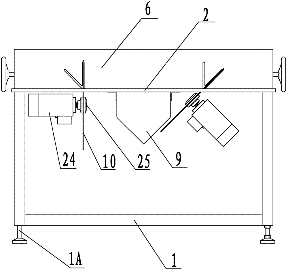
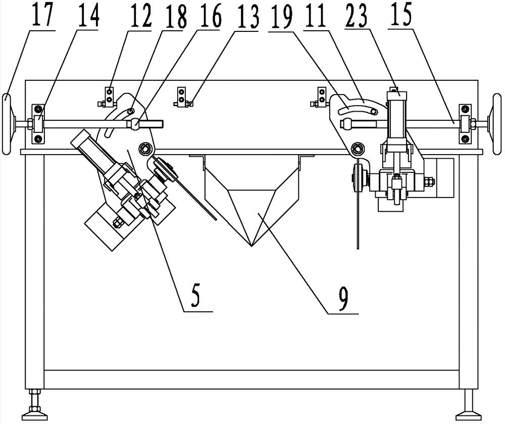
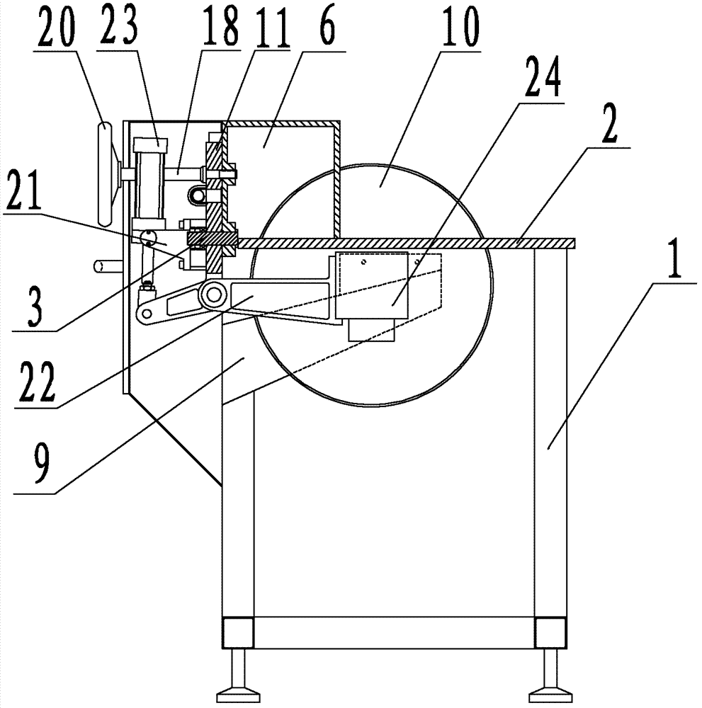
[0027] Example 1: Please refer to Figure 1 to Figure 4 , the present invention comprises a frame 1, a frame foot 1A, a workbench 2, a rotating shaft 3, a longitudinal axis 4, a power head 5, a box 6, a relief groove 7, a blanking hole 8, a discharge guide groove 9, a saw Sheet 10, corner plate 11, positioning seat 12, adjusting screw 13, corner screw seat 14, corner screw 15, corner nut 16, corner handwheel 17, plane compression screw 18, plane compression screw relief groove 19, plane pressure Tight hand wheel 20, bearing 21, swing arm 22, feed cylinder 23, motor 24, motor shaft 25. The corner device and plane pressing device of this embodiment are manual structures, the bottom of the frame 1 is supported by the frame feet 1A and supports the workbench 2 upwards, and the two rotating shafts 3 are divided into left and right sides in the direction of the longitudinal axis 4. It is placed on the rear lower part of the box 6 added at the rear of the workbench 2 in a ground and...

Embodiment 2

[0028] Example 2: Please refer to Figure 5 to Figure 8 , the present invention comprises a frame 1, a frame foot 1A, a workbench 2, a rotating shaft 3, a longitudinal axis 4, a power head 5, a box 6, a relief groove 7, a blanking hole 8, a discharge guide groove 9, a saw Sheet 10, corner plate 11, positioning seat 12, adjustment screw 13, plane pressing screw relief slot 19, support 21, swing arm 22, feed cylinder 23, motor 24, motor shaft 25, corner cylinder 26, plane pressure Tightening screw 27, cylinder block 28, rotation compression cylinder 29, compression pin 30, compression surface 31, main shaft 32, motor shaft pulley 33, main shaft pulley 34, belt 35. The corner device and the rotary pressing device of the present embodiment are pneumatic structures, and the corner cylinder 26 acts on the upper part of the corner plate 11 with the box 6 as a fulcrum, and the plane pressing screw 27 passes through the plane pressing screw give way groove 19 to float and press. The c...


PUM


Abstract

The invention discloses a double-end combined cutting machine. The double-end combined cutting machine comprises a stand and a workbench, wherein the stand supports the workbench, the workbench is integral, a left rotary shaft and a right rotary shaft are horizontally arranged at the rear part of the workbench in parallel in a direction of a longitudinal shaft, a left power head and a right power head are respectively arranged on the left rotary shaft and the right rotary shaft in reverse directions and can rotate at certain angles respectively around the rotary shafts, each power head comprises a power device, each power device comprises a swinging arm, a motor and a saw bit, the motors are arranged at the front parts of the swinging arms, the saw bits are arranged on motor shafts, the motor of the left power head is characterized in that a motor body is arranged on the left while the motor shaft is arranged on the right, and the motor of the right power head is characterized in that the motor body is arranged on the right while the motor shaft is arranged on the left. The double-end combined cutting machine overcomes defects that various cutting modes can not be realized by once material feeding when the traditional sectional material is cut by a device only with one power head, and enriches the forms of product structures.

Description

technical field [0001] The invention relates to mechanical processing equipment, in particular to a double-head combined cutting machine. Background technique [0002] Existing cutting machines for processing profiles with bevels only have one power head on one frame. Although these cutting machines can swing angles to process bevels, if it is specified that one side of the profile is used as a reference for irregular For example, (1) the left port is positively beveled, the right port is vertical, (2) the left port is vertical, the right port is negatively beveled, (3) the left port is positively beveled, the right port is negatively beveled . In the above-mentioned situations, it is necessary to frequently adjust the sawing angle of the power head to cut the profile, resulting in interruption of the cutting process and multiple conveying and clamping of the profile, which greatly reduces the work efficiency. Contents of the invention [0003] In view of the shortcoming...

Claims


Application Information

Patent Timeline
Patent Type & Authority Applications(China)
IPC IPC(8): B23D45/10B23D47/02B23D47/12B23D47/10
Inventor 翟秋朗翟伟军
Owner 翟秋朗
Learn More