
Control method of high-voltage electrostatic dedusting energy-saving device

A high-voltage electrostatic and control method technology, applied in the direction of electrostatic separation, power supply technology, etc., can solve problems such as large temperature difference, waste of electric energy, damage to porcelain sleeves, porcelain shafts, etc., and achieve the effects of prolonging life, reducing maintenance costs, and saving energy.

Inactive Publication Date: 2012-10-17
ZHEJIANG JIUDA ENVIRONMENTAL PROTECTION EQUIPCO
View PDF6 Cites 5 Cited by
  • Summary
  • Abstract
  • Description
  • Claims
  • Application Information

AI Technical Summary

Problems solved by technology

[0002] The existing high-voltage electrostatic precipitator energy-saving equipment usually includes a controller, and the controller includes a control chip, a multi-channel sensor, a multi-channel communication interface, a step-up transformer drive circuit, a rapping motor drive circuit, and a plurality of electric heater drive circuits. The circuit and the control chip are respectively connected to the multi-channel sensor, the multi-channel communication interface, the step-up transformer drive circuit, the rapping motor drive circuit, and multiple electric heater drive circuits. In the control method of the prior art, the control chip is connected to the The step-up transformer drive circuit, the rapping motor drive circuit, and multiple electric heater drive circuits output control signals. Among them, the control of multiple electric heaters adopts conventional, constant temperature control, and there is no pre-output electric heating program. Since there is no pre-heating If the temperature difference between the inside and the outside of the electric field is large, coldness will appear on the porcelain bushing and the porcelain shaft. more power

Method used


Image

  • Control method of high-voltage electrostatic dedusting energy-saving device

Examples


Embodiment Construction

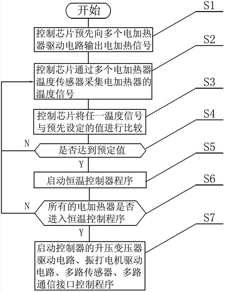
[0015] Such as figure 1 As shown, a control method for high-voltage electrostatic precipitator and energy-saving equipment is applied to a high-voltage electrostatic precipitator energy-saving controller. drive circuit, multiple electric heater drive circuits, the control chip is respectively connected with multiple sensors, multiple communication interfaces, step-up transformer drive circuits, rapping motor drive circuits, multiple electric heater drive circuits, the controller’s The control method comprises the steps of:

[0016] The S1 control chip outputs electric heating signals to multiple electric heater drive circuits in advance;

[0017] The S2 control chip collects the temperature signal of the electric heater through multiple electric heater temperature sensors;

[0018] The S3 control chip compares any temperature signal with a preset value;

[0019] S4 judges whether to reach predetermined value, if not, repeat step S2; If yes,

[0020] S5 starts the constant ...


PUM


Abstract

The invention discloses a control method of a high-voltage electrostatic dedusting energy-saving device. The control method which is applied to a high-voltage electrostatic dedusting energy-saving controller comprises the following steps: 1, a control chip outputs an electric heating signal to a plurality of electric heater driving circuits in advance; 2, the control chip acquires temperature signals of the electric heaters through a plurality of electric heater heat sensors; 3, the control chip compares anyone of the temperature signals with a preset value; 4, whether the compared temperature signal reaches the preset value is judged, step 2 is repeatedly carried out if not, and step 5 is carried out if so; 5, constant temperature control programs are started; 6, whether all the electric heaters enter the constant temperature control programs is judged, the step 2 is repeatedly carried out if not, and step 7 is carried out if so; and 7, the step up transformer drive circuit, the rapping motor drive circuit, the sensors and the multipath communication interface control programs of the controller are started. The control method has the beneficial effects of electric heater life prolongation, maintenance cost reduction and energy saving.

Description

technical field [0001] The invention relates to a control method for high-voltage electrostatic dust removal and energy-saving equipment, and belongs to the field of environmental protection equipment. Background technique [0002] The existing high-voltage electrostatic precipitator energy-saving equipment usually includes a controller, and the controller includes a control chip, a multi-channel sensor, a multi-channel communication interface, a step-up transformer drive circuit, a rapping motor drive circuit, and a plurality of electric heater drive circuits. The circuit and the control chip are respectively connected to the multi-channel sensor, the multi-channel communication interface, the step-up transformer drive circuit, the rapping motor drive circuit, and multiple electric heater drive circuits. In the control method of the prior art, the control chip is connected to the The step-up transformer drive circuit, the rapping motor drive circuit, and multiple electric h...

Claims


Application Information

Patent Timeline
IPC IPC(8): B03C3/68
Inventor 方泉
Owner ZHEJIANG JIUDA ENVIRONMENTAL PROTECTION EQUIPCO
Learn More