Method and device for enumerating input/output devices

An input and output device, enumeration technology, applied in the direction of program control design, multi-programming device, instrument, etc., can solve problems such as increasing product cost, prolonging system startup time, reducing product design efficiency, etc., to achieve accelerated process, The effect of reducing the time spent

Active Publication Date: 2013-11-06
XFUSION DIGITAL TECH CO LTD
View PDF3 Cites 0 Cited by
  • Summary
  • Abstract
  • Description
  • Claims
  • Application Information

AI Technical Summary

Problems solved by technology

However, this process will take a lot of time and prolong the system start-up time. Users can use the system normally after the system starts for a long time, which will reduce the user's satisfaction with the system and product recognition.
In addition, in the product design and development stage, the system will be restarted repeatedly to verify whether a certain modification takes effect, and to check the system function and performance. If the system starts for a long time, the efficiency of product design and development will be reduced, thereby increasing product costs. , reducing product competitiveness

Method used


Image

  • Method and device for enumerating input/output devices
  • Method and device for enumerating input/output devices
  • Method and device for enumerating input/output devices

Examples


Embodiment 1

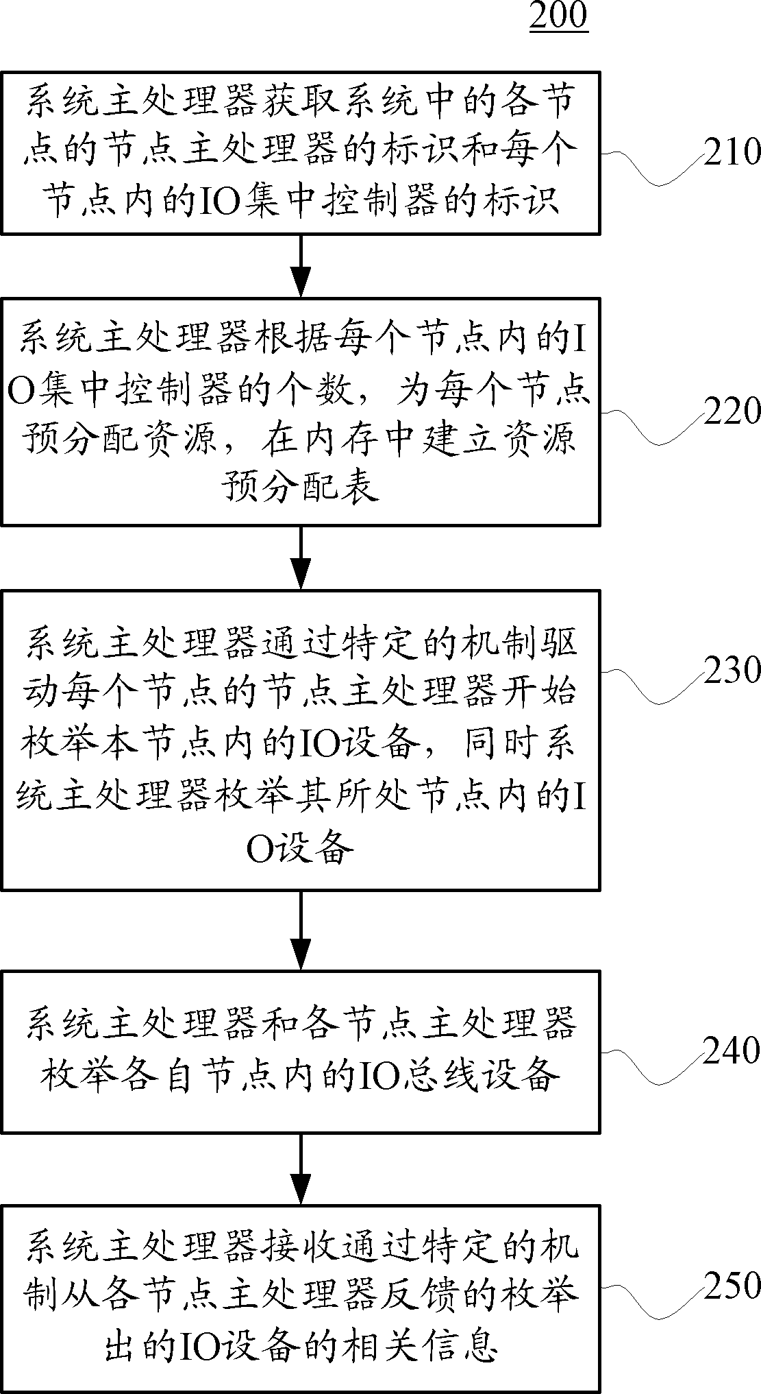
[0033] figure 2is a flow chart of the method 200 for enumerating IO devices in the system according to Embodiment 1 of the present invention. The method 200 in Embodiment 1 is suitable for use in a hardware system architecture with multiple nodes. As mentioned above, there is a Node Master Processor for each node to handle node-level transactions within that node. In addition, there is also a processor called the system main processor in the system. As the highest-level processor in the system, it is responsible for system-level affairs. At the same time, the system main processor is also the node main processor of the node where it is located. It should be noted that the main processor of the system and the main processor of the node are selected by the system through a certain mechanism. Other software of the system (such as system management software) specifies which processor becomes the main processor of the system and which processors become the main processors of the...

Embodiment 2

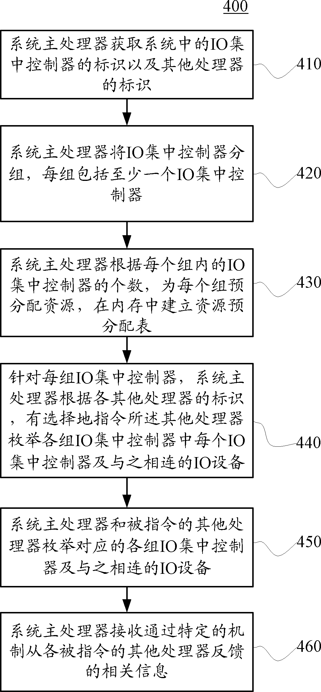
[0057] Embodiment 2 of the present invention differs from Embodiment 1 in that the hardware system architecture in Embodiment 2 does not have a clear node concept, for example, there is only one node in the hardware system architecture. In this hardware system architecture, the grouping of IO centralized controllers and the selection of processors used to enumerate each group of IO centralized controllers and the IO devices connected thereto have greater flexibility. Figure 4 It is a flowchart of a method 400 for enumerating IO devices according to Embodiment 2 of the present invention. Specifically described as follows, the method 400 includes:

[0058] 410: The main processor of the system acquires the identifier of the IO centralized controller and the identifiers of other processors in the system. Of course, the main processor of the system can also obtain its own identification. Similar to Embodiment 1, the main processor of the system may also obtain information about...


PUM


Abstract

Embodiments of the present disclosure relate to a method and a device for enumerating input / output devices (IO devices). The method for enumerating input / output devices includes: acquiring an identifier of each processor and an identifier of each input / output (IO) centralized controller in a system; separately instructing processors to simultaneously enumerate a specific IO centralized controller and an input / output IO device connected to the specific IO centralized controller, according to the identifier of each processor and the identifier of each IO centralized controller; and acquiring related information of IO devices enumerated by the instructed processors. According to the embodiments of the present disclosure, the work of enumerating the system IO devices may be allocated to multiple processors to be carried out simultaneously, so as to greatly reduce time consumed in the enumeration process, and to accelerate a system initialization process.

Description

technical field [0001] Embodiments of the present invention relate to hardware system architecture, and more specifically, to a method and device for enumerating input and output devices in a hardware system. Background technique [0002] Generally, in hardware system architecture, such as x86 and Itanium system hardware architecture, processors such as Central Processing Unit (Central Processing Unit, referred to as CPU) and input / output centralized controller (Input / Output Hub or Input / Output Controller Hub, referred to as IOH or ICH) are connected to each other through a bus for data transmission. Multiple processors and multiple IOHs may exist in the hardware system architecture at the same time, and each IOH may be connected to multiple input / output (Input / Output, IO for short) devices. Multiple bridge devices can be integrated within the IOH, and the bus drawn from the bridge device is connected to the processor through the first bus (Bus0) in the system. [0003] Ta...

Claims


Application Information

Patent Timeline
Patent Type & Authority Patents(China)
IPC IPC(8): G06F15/17G06F9/50
CPCG06F9/50G06F13/10G06F15/17G06F9/4405G06F13/00G06F9/4411
Inventor 刘云海朱冠宇
Owner XFUSION DIGITAL TECH CO LTD
Why Eureka
Try Eureka