Bearing type support frame for key
A support type and support frame technology, applied in the direction of instruments, electroacoustic musical instruments, etc., can solve problems such as easy deviation, and achieve the effect of avoiding depression, preventing unnecessary noise, and eliminating deviation problems.
- Summary
- Abstract
- Description
- Claims
- Application Information
AI Technical Summary
Problems solved by technology
Method used
Image
Examples
Embodiment 1
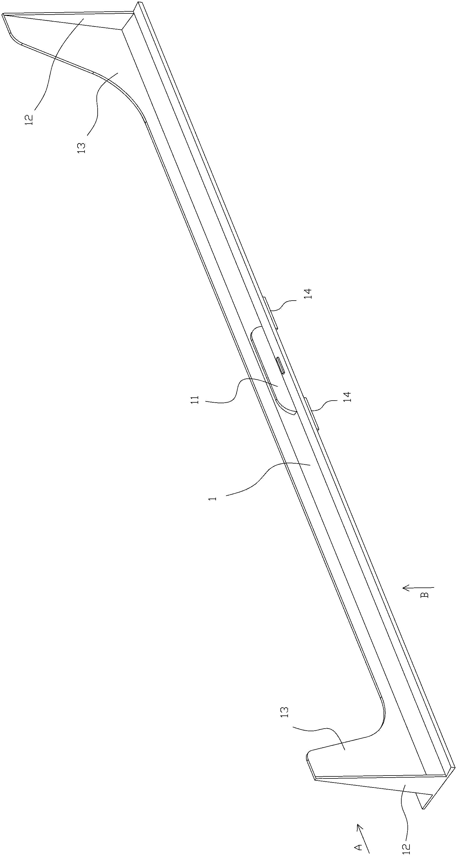
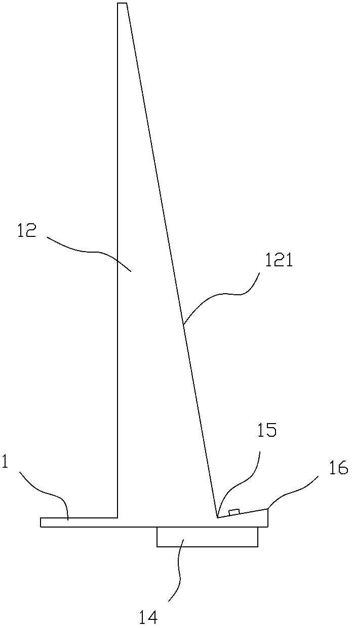
[0026] Such as Figure 1 to Figure 4 As shown, the key supporting frame includes a supporting plate 1 for supporting the housing 100 of the playing guidance device.
[0027] The top surface of the supporting plate 1 extends upwards with two support rods 12 for supporting the back of the housing 100 of the playing guidance device, and a positioning groove that can match the positioning groove at the bottom of the housing 100 of the playing guidance device. The protrusion 11 and the two support rods 12 are respectively located on the left and right sides of the supporting plate 1 , and the positioning protrusion 11 is located between the two support rods 12 .
[0028] As we all know, whether it is an electronic organ or a piano, such as Figure 4 As shown, there are black keys 201 and white keys 202 on the keys 200, and the distribution is that the white keys 202 are at the bottom, the black keys 201 are above the white keys 202, and the arrangement of the black keys 201 from l...
Embodiment 2
[0035] Such as Figure 5 to Figure 7 As shown, the difference between this embodiment and the first embodiment is that some circuit modules of the playing guidance device are integrated on the supporting plate. The details are as follows:
[0036] The key supporting frame includes a supporting plate 2 for supporting the casing 300 of the playing guidance device.
[0037] The top surface of the supporting plate 2 extends upwards with two support rods 22 for supporting the back of the housing 300 of the playing guidance device, and a positioning groove that can match the positioning groove at the bottom of the housing 300 of the playing guidance device. The protrusion 21 and the two support rods 22 are respectively located on the left and right sides of the supporting plate 2 , and the positioning protrusion 21 is located between the two support rods 22 .
[0038] The bottom surface of the supporting plate 2 extends downward with a positioning block 24, the width of the positi...
Embodiment 3
[0044] Such as Figure 8 and Figure 9 As shown, the difference between the present embodiment and the second embodiment lies in the structure of more functional component slots. The details are as follows:
[0045] The top surface of the supporting plate 2 also extends upwards with two functional component slots 26, and circuit contacts 261 are installed in the functional component slots 26, and the circuit contacts 261 are electrically connected with the single-chip microcomputer 303; a functional component The socket 26 is plugged with a functional component insert 400 , and the electrical contact piece 401 of the functional component insert 400 is connected with the circuit contact 261 .
[0046] The functional component insert 400 can be a memory card or a power module or a sound player.
[0047] That is to say, the power socket 305 of the second embodiment is canceled in this embodiment, and the functional component socket 26 is used to replace it. When the functiona...
PUM
 Abstract
Description
Claims
Application Information
 - Generate Ideas
- Intellectual Property
- Life Sciences
- Materials
- Tech Scout
- Unparalleled Data Quality
- Higher Quality Content
- 60% Fewer Hallucinations
Browse by: Latest US Patents, China's latest patents, Technical Efficacy Thesaurus, Application Domain, Technology Topic, Popular Technical Reports.
© 2025 PatSnap. All rights reserved.Legal|Privacy policy|Modern Slavery Act Transparency Statement|Sitemap|About US| Contact US: help@patsnap.com


