Method for directly calibrating micro thrust and micro impulse
A calibration method and micro-impulse technology, applied in the direction of weighing equipment testing/calibration, etc., can solve the problems of difficult calibration of thrust and impulse, large error, etc., and achieve the effect of large impulse calibration range, small error and high accuracy
- Summary
- Abstract
- Description
- Claims
- Application Information
AI Technical Summary
Problems solved by technology
Method used
Image
Examples
Embodiment Construction
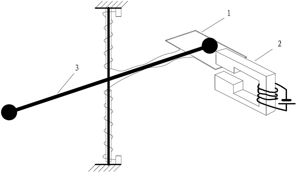
[0020] figure 1 Shown is a schematic diagram of the calibration method of torsional micro-thrust and micro-impulse, and the calibration steps are as follows:
[0021] 1. Place the force coil 1 (0.15mm enamelled copper wire, 20 turns) in the tray of the high-precision electronic scale, use an auxiliary device to keep it vertical and connect the force coil 1 with a known size Current; load a fixed current to the coil of the ring electromagnet 2 (or directly replace the ring electromagnet 2 with a ring-shaped permanent magnet with an air gap), and use an auxiliary device to keep the ring electromagnet 2 in a certain posture, so that a section of the force coil 1 The wire passes through the air gap of the ring electromagnet 2, and the force coil is subjected to a vertical upward or downward ampere force under the action of the air gap magnetic field. The length of the wire passing through the air gap is 10 mm, and the magnetic induction is 0.7 Tesla. If the current of the force c...
PUM
 Abstract
Description
Claims
Application Information
 - R&D
- Intellectual Property
- Life Sciences
- Materials
- Tech Scout
- Unparalleled Data Quality
- Higher Quality Content
- 60% Fewer Hallucinations
Browse by: Latest US Patents, China's latest patents, Technical Efficacy Thesaurus, Application Domain, Technology Topic, Popular Technical Reports.
© 2025 PatSnap. All rights reserved.Legal|Privacy policy|Modern Slavery Act Transparency Statement|Sitemap|About US| Contact US: help@patsnap.com

