Trolley traction device

The technology of a traction device and a trolley is applied in the directions of furnaces, lighting and heating equipment, furnace components, etc., which can solve the problems of shortening the service life of the trolley, large workload and labor cost, and cooling deformation of the horn, and achieves a simple structure, The effect of reducing manufacturing and construction costs and preventing cold and heat deformation

Inactive Publication Date: 2012-10-10
WISDRI WUHAN WIS IND FURNACE
View PDF5 Cites 3 Cited by
  • Summary
  • Abstract
  • Description
  • Claims
  • Application Information

AI Technical Summary

Problems solved by technology

For the previous heating furnace trolley equipment, if the pin tooth transmission is used for transmission, the foundation of the drainage ditch must be dug. The heat-resistant shims and refractory bricks on the machine are both resistant to high temperatures, but the transmission device is sprayed with water immediately after it is released from the furnace, which will cause problems such as cracking of the refractory bricks and rapid cooling and deformation of the shims, thereby shortening the service life of the trolley and increasing costs.

Method used


Image

  • Trolley traction device

Examples


Embodiment 1

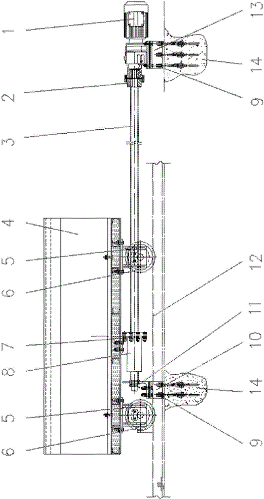
[0019] A trolley traction device, such as figure 1 As shown, it includes a motor 1, a coupling 2, a ball screw 3, a support frame 7, a ball screw pair 8, an anchor bolt 9, a fixed base 10, a support 11 and a motor support 13; the fixed base 10 passes through The anchor bolt 9 is fixed to the foundation 14 in the middle of the two parallel rails 12, the support 11 is fixed on the fixed base 10; the motor support 13 is fixed on the foundation 14 through the anchor bolt 9, and the motor 1 is fixed on the motor support 13 Above; the ball screw pair 8 is screwed on the ball screw 3 (the ball screw pair is equivalent to a nut), the right end of the ball screw 3 is connected with the output shaft of the motor 1 through the coupling 2, and the left end of the ball screw 3 is placed On the support 11 , the ball screw 3 is parallel to the rail 12 ; the ball screw pair 8 is fixedly connected to the bottom of the trolley frame 4 by the support frame 7 .

[0020] According to the above so...

Embodiment 2

[0024] A trolley traction device, such as figure 1 As shown, it includes a motor 1, a coupling 2, a ball screw 3, a support frame 7, a ball screw pair 8, an anchor bolt 9, a fixed base 10, a support 11 and a motor support 13; the fixed base 10 passes through The anchor bolt 9 is fixed to the foundation 14 in the middle of the two parallel rails 12, the support 11 is fixed on the fixed base 10; the motor support 13 is fixed on the foundation 14 through the anchor bolt 9, and the motor 1 is fixed on the motor support 13 Above; the ball screw pair 8 is screwed on the ball screw 3 (the ball screw pair is equivalent to a nut), the right end of the ball screw 3 is connected with the output shaft of the motor 1 through the coupling 2, and the left end of the ball screw 3 is placed On the support 11 , the ball screw 3 is parallel to the rail 12 ; the ball screw pair 8 is fixedly connected to the bottom of the trolley frame 4 by the support frame 7 .

[0025] According to the above sc...


PUM


Abstract

The invention relates to a trolley traction device. The trolley traction device is characterized by comprising a motor, a coupler, a ball screw, a supporting bracket, a ball screw pair, a foundation bolt, a fixed base, a strut and a motor supporting seat; the fixed base is fixed on foundation in the middle of two parallel steel rails through the foundation bolt, and the strut is fixed on the fixed base; the motor supporting seat is fixed on the foundation through the foundation bolt, and the motor is fixed on the motor supporting seat; the ball screw pair is screwed onto the ball screw, the right end of the ball screw is connected with an output shaft of the motor through the coupler, the left end of the ball screw is arranged on the strut, and the ball screw is parallel to the steel rails; and the ball screw pair is fixedly connected with the bottom of a trolley frame through the supporting bracket. The trolley traction device is simple in structure, convenient to construct, install and repair, less in the manufacturing and construction cost, and high in transmission precision and transmission efficiency.

Description

technical field [0001] The invention belongs to the technical field of trolley-type heating furnaces, and in particular relates to a trolley traction device. Background technique [0002] The trolley is used in the trolley-type heating furnace. The body consists of three parts: refractory material, frame and walking mechanism. The trolley is generally used to load the heated steel ingot or billet. The loading capacity is large, the temperature is high, and the operation of entering and exiting the furnace is frequent. The trolley is required to have high strength, rigidity and thermal creep resistance. It has better sealing. For the previous heating furnace trolley equipment, if the pin tooth transmission is used for transmission, the foundation of the drainage ditch must be dug. The heat-resistant shims and refractory bricks on the machine are resistant to high temperatures, but the transmission device is sprayed with water immediately after being released from the furnac...

Claims


Application Information

Patent Timeline
Patent Type & Authority Applications(China)
IPC IPC(8): F27D3/12
Inventor 余飞段广东
Owner WISDRI WUHAN WIS IND FURNACE
Why Eureka
Try Eureka