
Wavelength conversion device and light-emitting device

A wavelength conversion device and light-emitting device technology, applied in the field of light source, can solve problems such as narrow application range, difficult coating, discounted application effect, etc., and achieve high brightness effect

Active Publication Date: 2012-10-10
APPOTRONICS CORP LTD
View PDF6 Cites 7 Cited by
  • Summary
  • Abstract
  • Description
  • Claims
  • Application Information

AI Technical Summary

Problems solved by technology

[0005] The above-mentioned methods are the main methods to limit the etendue of the light source, and these methods have their own problems, which make their application effect greatly reduced
For example, in the method of using an angle-selective filter to limit the luminous angle, the angle-selective filter uses the characteristics that the filter has different transmission lines for light at different incident angles to achieve angle selection, but for light at different incident angles The difference in the transmission spectral lines cannot be very large, so it cannot work well for broad-spectrum light, and the stimulated emission of wavelength conversion materials is often broad-spectrum light
For BEF, although its working principle has nothing to do with wavelength, its limited angle is determined, about 20-30 degrees, and other angle restrictions cannot be realized, so its application range is narrow
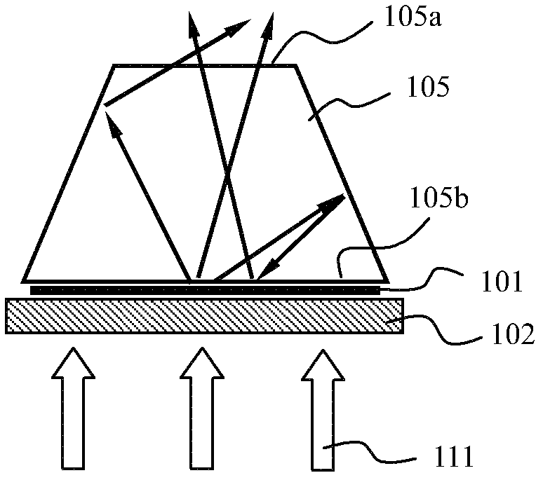
As for the method of using reflective devices to reduce the light-emitting area, its efficiency directly depends on the reflectivity of the sides of the reflective device, and these sides are often steep, which causes great difficulties for coating

Method used


Image

  • Wavelength conversion device and light-emitting device
  • Wavelength conversion device and light-emitting device
  • Wavelength conversion device and light-emitting device

Examples


Embodiment Construction

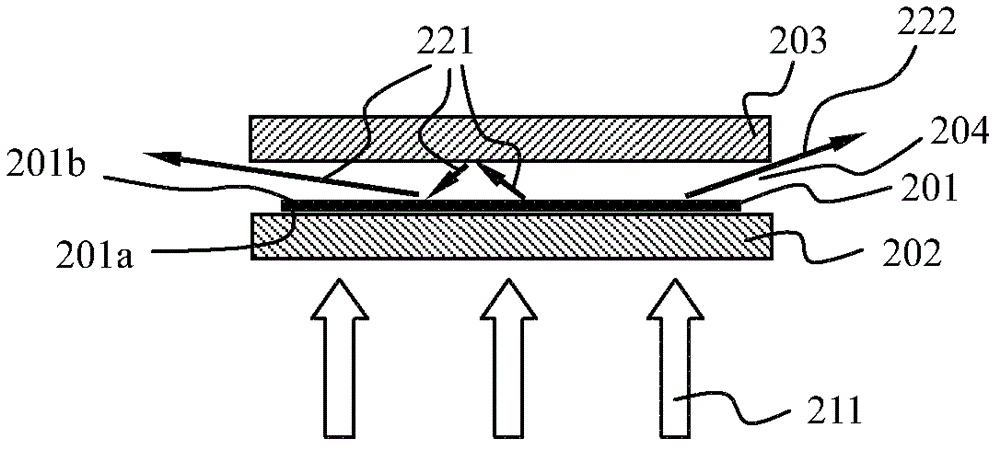
[0018] The wavelength conversion device of the first embodiment of the present invention is as follows figure 2 As shown, it includes a wavelength conversion layer 201 for absorbing excitation light and emitting laser light, the wavelength conversion layer 201 includes a first surface 201a and a second surface 201b opposite; The spectroscopic filter device 202 on the side, the spectroscopic filter device 202 can transmit the excitation light 211 and reflect the received laser light; it also includes a reflection device 203 located on one side of the second surface 201b of the wavelength conversion layer for reflecting the received laser light; also includes The light extraction layer 204 located between the spectroscopic filter device 202 and the reflection device 203 emits from at least a part of the side surface of the light extraction layer 204 . The thickness of the light extraction layer 204 is less than or equal to 45% of the radius of the circumscribed circle of the li...


PUM


Abstract

The invention brings forward a wavelength conversion device and a light-emitting device in which the wavelength conversion device is applied. The wavelength conversion device comprises a wavelength conversion layer which is used for absorbing exciting light and emitting stimulated light, and further comprises a light splitting and filtering device which is positioned on one side of the first surface of the wavelength conversion layer, and a reflection device which is used for reflecting the stimulated light and is positioned in one side of the second surface of the wavelength conversion layer. The wavelength conversion device further comprises a light extraction layer which is positioned between the light splitting and filtering device and the reflection device, wherein the thickness of the light extraction layer is less than or equal to 45% of the circumradius of a light spot formed on the wavelength conversion layer by the exciting light. With the wavelength conversion device and the light-emitting device of the invention, and by using the restriction on the thickness of the light extraction layer and the reflection of the stimulated light between the reflection device and the light splitting and filtering device, the decrease speed of the luminous flux of the light emitted from the side surface of the light extraction layer is lower than the decrease speed of etendue, and therefore the light has high brightness.

Description

technical field [0001] The present invention relates to the field of light sources, in particular to a wavelength conversion device and a light-emitting device based on the wavelength conversion device. Background technique [0002] At present, semiconductor light sources based on wavelength conversion materials have been paid more and more attention. This is mainly caused by the high efficiency of wavelength converting materials. For example, US Pat. No. 7,547,114 proposes a light source structure, which uses excitation light emitted by an excitation light source to excite a wavelength conversion material turntable, and uses the rotation of the turntable to make wavelength conversion materials of different colors excited by the excitation light in turn to generate light sequences of different colors . Patent US7547114 also mentioned that placing an angle selection filter on the side of the wavelength conversion material away from the excitation light can limit the etendue...

Claims


Application Information

Patent Timeline
IPC IPC(8): F21V9/10F21V9/40
Inventor 李屹杨毅
Owner APPOTRONICS CORP LTD
Learn More