Method and device for automatically controlling temperature of optical fiber coatings in wiredrawing process

An automatic control device and a technology of drawing process, applied in the field of optical fiber processing, can solve problems such as difficulty in meeting the requirements of high-speed drawing coating, difficulty in ensuring the quality of optical fiber coating, etc., achieving easy implementation and promotion, simple structure, and avoiding paint overflow. Effect

Active Publication Date: 2012-10-10
SICHUAN LEFEI OPTOELECTRONICS TECH CO LTD
View PDF3 Cites 8 Cited by
  • Summary
  • Abstract
  • Description
  • Claims
  • Application Information

AI Technical Summary

Problems solved by technology

In this case, it is more and more difficult to meet the requirements of high-speed wire drawing for coating coating by using the traditional fixed temperature heating method, and it is difficult to guarantee the coating quality of optical fibers

Method used


Image

  • Method and device for automatically controlling temperature of optical fiber coatings in wiredrawing process
  • Method and device for automatically controlling temperature of optical fiber coatings in wiredrawing process

Examples


Embodiment 1

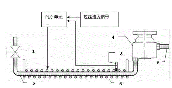
[0024] Example 1 as figure 1 As shown, it is an electric heating method, including an optical fiber coater 4, and the coating chamber of the optical fiber coater communicates with the material tank through a feed pipe, and the described optical fiber coater is provided with two coating chambers, upper and lower, wherein The upper paint chamber is connected with the upper feed pipe 5, and the upper feed pipe may or may not be provided with a controllable heater, and the lower paint chamber is connected with the lower feed pipe 2, and the outer surface of the lower feed pipe is wound with one layer or more A layer of heating wire constitutes a controllable heater 6, and the temperature of the lower feeding pipeline is measured by a temperature sensor 3. At the same time, the temperature of the heating wire is adjusted by the temperature setting value of the PLC unit connected to it, and the temperature setting value is according to the formula 1 is set, and the wire drawing spee...

Embodiment 2

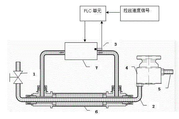
[0026] Example 2 as figure 2 As shown, the liquid or gas medium heating method differs from the previous embodiment in that the controllable heater 6 is a liquid or gas medium heater, and the liquid or gas medium heater is covered by The annular heating tank of the feed pipeline 2 and the circulation heater 7 connected thereto are formed. The annular heating tank and the circulation heater are filled with liquid or gas medium, and the circulation heater heats the feed pipeline by heating the liquid or gas medium to make the paint Raise the temperature until the coating temperature is close to the temperature of the liquid or gas medium; the temperature sensor of this embodiment is installed in the liquid or gas medium cavity of the circulating heater, and the temperature of the liquid or gas medium is used as the temperature sensing of the feed pipeline to the PLC unit. Other structures are the same as the previous embodiment.


PUM


Abstract

The invention relates to a method and a device for automatically controlling the temperature of optical fiber coatings in a wiredrawing process. The device comprises an optical fiber coating device, wherein a coating cavity of the optical fiber coating device is communicated with a charging bucket by a charging pipeline. The device is characterized in that the charging pipeline is externally provided with a controllable heater which is used for heating the coatings in the charging pipeline, the charging pipeline is externally provided with a processing control unit which is used for comparing an acquired wiredrawing speed sensing signal and charging pipeline temperature sensing signal with a preset parameter numerical value, so as to control the heating process of the controllable heater, so that the automatic controlling and adjusting process of the temperate of the coatings in the optical fiber coating device can be realized. According to the device and the method, the temperature of the coatings can be automatically changed along with the wiredrawing speed when the optical fiber is wiredrawn, so that the temperature (or the viscosity) of the coatings can be well matched with the wiredrawing speed, and therefore, the quality of a coating layer on the surface of the optical fiber can be guaranteed, and the machining yield of the optical fiber can be improved. The method and the device are simple in structure, and convenient to implement and popularize, so that the automatic level of optical fiber machining equipment can be improved.

Description

technical field [0001] The invention relates to a method and a device for online temperature control of optical fiber coatings in a wet-on-wet coating process, belonging to the technical field of optical fiber processing. Background technique [0002] Optical fiber coating is one of the two most important materials that make up the optical fiber. Its main functions include mechanical protection of the bare optical fiber, maintaining the strength of the optical fiber, resisting environmental erosion, and maintaining and improving the bending performance of the optical fiber. Therefore, the quality of optical fiber coating will directly affect the quality and performance of optical fiber. For conventional communication optical fibers, the surface of the glass optical fiber is coated with two coating layers. The thickness and proportion distribution of the two coating layers will greatly affect the performance of the optical fiber, such as peeling force, microbending performanc...

Claims


Application Information

Patent Timeline
Patent Type & Authority Applications(China)
IPC IPC(8): C03C25/20
CPCC03C25/20C03C25/12
Inventor 向德成张华明何勤国钱新伟王瑞春陈刚
Owner SICHUAN LEFEI OPTOELECTRONICS TECH CO LTD
Why Eureka
Try Eureka