Column A of automobile with movable roof and automobile with movable roof
A technology of movable roof and automobile, applied in the direction of vehicle parts, superstructure, sub-assembly of superstructure, etc., can solve the problems of insufficient torsional bending stiffness, insignificant effect, low safety performance of automobiles, etc., so as to improve the bearing capacity and strengthen the and protective effect
- Summary
- Abstract
- Description
- Claims
- Application Information
AI Technical Summary
Problems solved by technology
Method used
Image
Examples
Embodiment 1
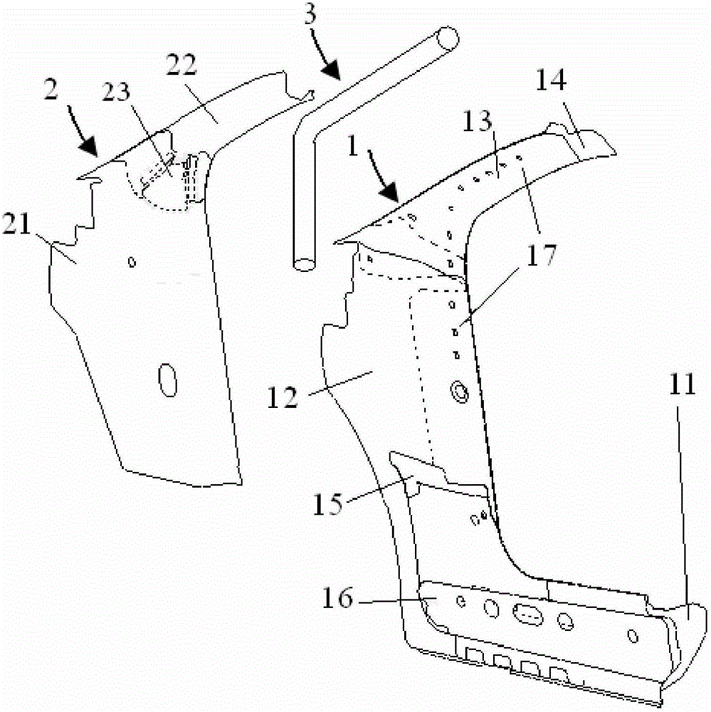
[0022] This embodiment provides an A-pillar of a movable roof automobile, see figure 1 , the A-pillar of the movable roof car includes: A-pillar outer panel assembly 1 and A-pillar inner panel assembly 2, A-pillar outer panel assembly 1 and A-pillar inner panel assembly 2 have a structure that is close to each other and strengthens each other. The A-pillar outer panel assembly 1 and the A-pillar inner panel assembly 2 are fixedly connected by welding to form an A-pillar assembly structure with greatly improved rigidity and strength. As other embodiments, the A-pillar outer panel assembly 1 and the A-pillar inner panel assembly 2 may also be fixedly connected by means of bolt connection, snap-in connection, continuous laser welding or structural adhesive connection.
[0023] A-pillar outer panel assembly 1 includes side wall outer panel 11, A-pillar lower reinforcement panel 12, A-pillar upper reinforcement panel 13 and A-pillar outer panel 14, side wall outer panel 11, A-pilla...
Embodiment 2
[0026] This embodiment provides an A-pillar of a movable roof automobile, see figure 1, the A-pillar of the convertible roof automobile includes an A-pillar outer panel assembly 1 and an A-pillar inner panel assembly 2, and the respective structures, assembling and connection relations of the A-pillar outer panel assembly 1 and the A-pillar inner panel assembly 2 are the same as in Embodiment 1 Similarly, the A-pillar of this embodiment also includes a reinforcing round tube 3, and the reinforcing round tube 3 is fixed between the A-pillar outer panel assembly 1 and the A-pillar inner panel assembly 2, and is connected with the A-pillar outer panel assembly 1 and the A-pillar The inner panel assemblies 2 are all welded or riveted or bolted. The reinforcing round tube 3 is processed into a folded shape, that is, the reinforcing round tube 3 includes a first section fixedly connected with the A-pillar lower reinforcement plate 12 and a second section fixedly connected with the A...
Embodiment 3
[0029] This embodiment provides an A-pillar of a movable roof automobile, see figure 1 , the A-pillar of the convertible roof car includes the A-pillar outer panel assembly 1, the A-pillar inner panel assembly 2 and the reinforced round tube 3, the A-pillar outer panel assembly 1, the A-pillar inner panel assembly 2 and the reinforced round tube 3 respectively The structure and assembly connection relationship are the same as in the second embodiment. The A-pillar outer panel assembly 1 of the A-pillar in this embodiment also includes a threshold front reinforcement plate 15 and a threshold rear reinforcement plate 16, and the threshold front reinforcement plate 15 and the threshold rear reinforcement plate 16 are welded to the side wall outer panel 11 and under the A-pillar for reinforcement. plate 12. In this way, the strength of the root of the A-pillar and the bearing capacity of the entire lower part of the A-pillar are greatly improved. As other embodiments, the front ...
PUM
 Abstract
Description
Claims
Application Information
 - R&D Engineer
- R&D Manager
- IP Professional
- Industry Leading Data Capabilities
- Powerful AI technology
- Patent DNA Extraction
Browse by: Latest US Patents, China's latest patents, Technical Efficacy Thesaurus, Application Domain, Technology Topic, Popular Technical Reports.
© 2024 PatSnap. All rights reserved.Legal|Privacy policy|Modern Slavery Act Transparency Statement|Sitemap|About US| Contact US: help@patsnap.com


