
Method for Realizing Controllable Gray Scale of LED Constant Current Driver and Constant Current Driver

A constant current driver and gray scale technology, applied in the level controllable field, can solve the problems of reducing the scope of application of the chip, low clock frequency utilization, cumbersome control, etc.

Active Publication Date: 2015-11-04
禹德芯电子科技(上海)有限公司
View PDF6 Cites 0 Cited by
  • Summary
  • Abstract
  • Description
  • Claims
  • Application Information

AI Technical Summary

Problems solved by technology

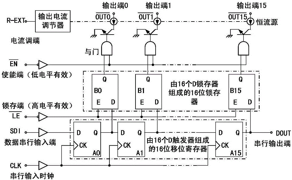
[0015] 1. For the LED driver without built-in PWM function, the data signal itself has no weight. If it is not used with EN, it can only convert the data signal itself into a duty cycle signal for grayscale display. This mode is subject to the highest limit of the chip itself. Due to the limitation of clock frequency, the displayed gray levels are quite limited, and this scheme has basically been eliminated;
[0016] 2. When the LED driver without built-in PWM uses the EN signal to indicate the data weight; at this time, the two signals of the data signal SDI and the EN signal are required to complete the display of gray levels, so that the control signals must be strictly corresponding. The circuit requires high precision, and the control is cumbersome;
Due to the low utilization rate of the clock frequency, this directly leads to a low amount of useful data transmission, so if the comparison is made with the same amount of useful data, more clock frequencies are needed to complete the input of these data
Since the highest clock frequency that the chip can withstand is limited (generally, drivers work in cascade, and the level of operating frequency affects the length of the cascade), so it also limits the length of the driver cascade, which not only increases Reduce the cost of the LED display screen and reduce the scope of application of the chip

Method used

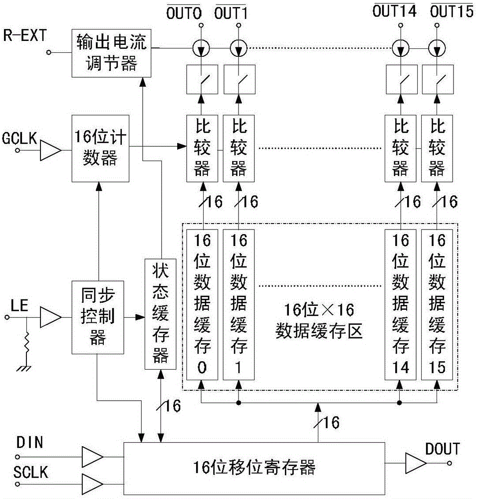
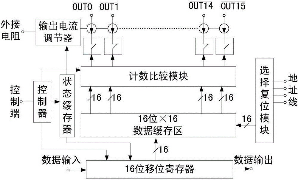

Image

  • Method for Realizing Controllable Gray Scale of LED Constant Current Driver and Constant Current Driver
  • Method for Realizing Controllable Gray Scale of LED Constant Current Driver and Constant Current Driver
  • Method for Realizing Controllable Gray Scale of LED Constant Current Driver and Constant Current Driver

Examples


Embodiment Construction

[0046] Hereinafter, preferred embodiments of the present invention will be described in detail with reference to the accompanying drawings. It should be understood that the preferred embodiments are only for illustrating the present invention, but not for limiting the protection scope of the present invention.

[0047] In the present invention, at first the following concepts are clarified:

[0048] The weight of binary data (also known as bit weight): Indicates the proportion of a certain binary number in the entire binary data, such as a 5-digit binary number (a4a3a2a1a0), where a4, a3, a2, a1, and a0 correspond to The weights are in order: 2 4 ,2 3 ,2 2 ,2 1 ,2 0 .

[0049] Expression of grayscale: The first way is the level of grayscale, that is, how many different levels of grayscale there are, such as the common 256-level grayscale, 1024-level grayscale, etc.; the second way is to use weighted Binary numbers are used to represent the gray scale, which is called ho...


PUM


Abstract

The invention discloses a method for realizing gray scale controllability of an LED (Light-Emitting Diode) constant-current driver. The method comprises the following steps of: according to a needed gray scale, controlling digits for storing data of data registers; when m gray scales (m(n) are needed, storing the data by the m data registers; resetting and zeroing to enable the data stored in residual (n-m) data registers to be zero so as to obtain the data type of the gray scale; and transmitting the data to a counting comparison module in parallel by the n data registers to generate a corresponding duty ratio signal driving output. According to the invention, the defects in the prior art are overcome; an LED driver is applicable to random display of 1-16-bit gray scales and a shifting register does not need to be fully filled; a chip can sufficiently utilize a clock frequency so that the requirements of the chip on the clock frequency are reduced; the cascading working capability of the chip of the driver is stronger; and furthermore, the invention further discloses the LED constant-current driver capable of realizing the gray scale controllability.

Description

technical field [0001] The invention relates to a method for realizing controllable gray levels of LED constant current drivers. Specifically, this design is based on shift registers, D flip-flops, counters and comparators to realize LED driving functions, and at the same time has gray levels that can be controlled. control function. Background technique [0002] The LED display screen is an important part of the LED field. Since the birth of the full-color LED display screen, it has maintained a rapid development trend. The full-color high-brightness LED large-screen display screen has been widely used in finance, securities, transportation, airports, railways, stadiums, Various fields such as commercial advertisement and post and telecommunications. The biggest feature of LED display is that its manufacturing is not limited by area, it can reach tens or even hundreds of square meters, and it is widely used in various indoor and outdoor occasions to display text, graphics,...

Claims


Application Information

Patent Timeline
Patent Type & Authority Patents(China)
IPC IPC(8): G09G3/32
Inventor 王巍杨铿黄展
Owner 禹德芯电子科技(上海)有限公司
Learn More