
Hydraulic aerial cage operation platform trajectory control device

An aerial work vehicle and trajectory control technology, which is applied in the direction of lifting device, control using feedback, safety device of lifting equipment, etc., can solve the problem of endangering the life safety of operators, the mathematical operation relationship of the rotation angle is not clearly given, and the error cannot be realized. Full compensation, etc.

Inactive Publication Date: 2012-10-03
DALIAN UNIV OF TECH +2
View PDF7 Cites 37 Cited by
  • Summary
  • Abstract
  • Description
  • Claims
  • Application Information

AI Technical Summary

Problems solved by technology

Specifically, there are the following four problems: First, the PWM signal in this patent acts on the proportional valve, and the proportional valve is a nonlinear link in the entire control, that is, the output flow of the proportional valve will not be proportional to the control current PWM value, Therefore, the maximum and minimum currents of the proportional valve are only measured through experiments. No matter how the PWM signal is adjusted, the control requirements described in the article will not be met, error compensation cannot be realized, and the control function cannot be realized; Theoretically, in the position control type I system of a typical valve-controlled cylinder with only negative feedback, when the signal after the trigonometric function operation is used as an input command, the execution system will generate a steady-state error, and the full compensation of the error cannot be realized; The third is that in realizing the ideal vertical lifting and horizontal telescopic movement described in this patent, no rotation angle is involved in the calculation
Fourth, the patent does not clearly provide the mathematical operation relationship between the slewing angle, the boom angle and the luffing angle
[0014] (2) There are potential safety hazards in the implementation of the patent
This control result may cause the operation platform to collide with adjacent high-altitude objects, which will not only cause equipment damage, but even endanger the life safety of operators and cause safety accidents
[0015] (3) The patent lacks the integrity of the motion control elements described
This patent only realizes the stability control of the action of a single mechanism, does not carry out the compound action control of the mechanism, and cannot realize the control of the operation platform along a specific linear trajectory

Method used

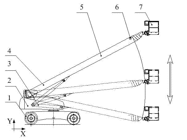

Image

  • Hydraulic aerial cage operation platform trajectory control device
  • Hydraulic aerial cage operation platform trajectory control device
  • Hydraulic aerial cage operation platform trajectory control device

Examples


Embodiment Construction

[0153] The present invention will be described in detail below in conjunction with the accompanying drawings and embodiments.

[0154] The track control device of the aerial work vehicle of the present embodiment includes the following parts:

[0155] 1. Operating mechanism

[0156] 1.1 Self-reset trajectory control enable button: the circuit is not connected under normal conditions, and the device is controlled by normal operation at this time. When the button is pressed, the intelligent trajectory control is enabled, and the normal normal operation control is blocked at the same time.

[0157] 1.2 The three-position rocker switch is used as a movement learning button and a movement reproduction button. On the premise that the self-resetting trajectory control enable button is pressed and held, the rocker switch is pressed to the upper position to start the motion learning function, and the controller can memorize the motion parameters (path, speed) of the aerial work vehic...


PUM


Abstract

The invention discloses a hydraulic aerial cage operation platform trajectory control device. The control device comprises an operation mechanism (A), a detection device (B), a display and alarm device (C), a hydraulic operation loop (D) with pressure compensation, a coordinate location module (E), a forward resolving module (F), a deflection compensation module (G), a speed setting module (H), an algorithm optimization module (I), and a programmable controller (J). The control device provided by the invention can significantly improve the work efficiency of the hydraulic aerial cage, reduce the labor intensity of operators, and lower the energy consumption as well as the use cost.

Description

technical field [0001] The invention relates to the field of high-altitude operation equipment with variable amplitude telescopic arms, in particular to a control device for an operation platform of an aerial work vehicle. Background technique [0002] The aerial work vehicle is a special engineering vehicle used to transport staff and equipment to a designated height for operations. The operating platform is a device for the work vehicle to carry staff and equipment in the air. The application object of the present invention is a straight-arm aerial work vehicle with a telescopic mechanism. The boom is driven by oil cylinders installed on the turntable and the boom at both ends to drive the luffing. The telescopic mechanism (such as rope row, sprocket, etc. etc.) to achieve. [0003] When the aerial work vehicle scrubs the glass up and down along the walls of high-rise buildings or installs objects sequentially along the top wall, or quickly reaches the designated operatin...

Claims


Application Information

Patent Timeline
Patent Type & Authority Applications(China)
IPC IPC(8): G05D3/12B66F11/04B66F17/00
Inventor 滕儒民刘鹏飞王欣曹旭阳王鑫王惠民
Owner DALIAN UNIV OF TECH
Learn More