An electrowetting display panel and its manufacturing method

A technology of electrowetting display and manufacturing method, applied in chemical instruments and methods, circuits, electrical components, etc., can solve the problems of affecting display effect, display difference, uneven thickness, etc., and achieve good display effect and difficult to display difference. Effect

Active Publication Date: 2015-11-18
BOE TECH GRP CO LTD
View PDF8 Cites 0 Cited by
  • Summary
  • Abstract
  • Description
  • Claims
  • Application Information

AI Technical Summary

Problems solved by technology

[0005] Embodiments of the present invention provide an electrowetting display panel and a manufacturing method thereof, which are used to solve the phenomenon that the thickness of the dielectric layer on the existing electrowetting display panel is prone to unevenness, which makes it easy to produce display differences and affect the display effect. question

Method used


Image

  • An electrowetting display panel and its manufacturing method
  • An electrowetting display panel and its manufacturing method
  • An electrowetting display panel and its manufacturing method

Examples


Embodiment Construction

[0046] In order to make the technical problems, technical solutions and advantages to be solved by the embodiments of the present invention clearer, the following will describe in detail with reference to the drawings and specific embodiments.

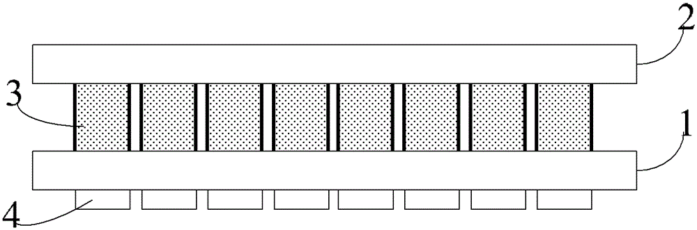
[0047] Such as figure 1 As shown, the embodiment of the present invention provides an electrowetting display panel, including:

[0048] The first glass substrate 1;

[0049] The second glass substrate 2 is arranged opposite to the first glass substrate 1;

[0050] The conductive colored liquid is filled in the chamber 3 arranged between the first glass substrate 1 and the second glass substrate 2. The chamber 3 can be surrounded by an insulating resin material. There are multiple chambers 3, and adjacent chambers chambers can be independent of each other (e.g. figure 1 shown), can also be connected to each other (not shown in the figure);

[0051] The reflective conductive device 4 is arranged on the surface of the first glass subs...


PUM


Abstract

Embodiments of the present disclosure provide an electrowetting display panel and the manufacturing method thereof The electrowetting display panel comprises: a first glass substrate; a second glass substrate provided opposite to the first glass substrate; a cavity provided between the first glass substrate and the second glass substrate; a colored conductive liquid filled into the cavity; and a reflecting conductive element provided on the surface of the first glass substrate facing away from the second glass substrate, and corresponding to the cavity, wherein the reflecting conductive element is used for controlling the light transmissivity of the colored conductive liquid within the cavity according to the voltage applied to the reflecting conductive element and reflecting the light passing through the colored conductive liquid toward the second glass substrate.

Description

technical field [0001] The invention relates to the technical field of electrowetting display, in particular to an electrowetting display panel and a manufacturing method thereof. Background technique [0002] The structure of the existing electrowetting display panel is that the first glass substrate and the second glass substrate are arranged oppositely, a plurality of reflective electrodes are formed on the surface of the first glass substrate facing the second glass substrate, and a plurality of reflective electrodes are formed above the electrodes. The dielectric layer is formed on the dielectric layer with a plurality of chambers corresponding to the electrodes one by one, and each chamber is filled with conductive colored liquid. [0003] The display principle of the above-mentioned electrowetting display panel is: using electrowetting phenomenon or electrochemical capillary phenomenon, when the conductive colored liquid in the chamber is subjected to the electric fie...

Claims


Application Information

Patent Timeline
Patent Type & Authority Patents(China)
IPC IPC(8): G02B26/02H01L21/77
CPCG02B26/005B32B37/14G02B26/02
Inventor 姚琪薛建设曹占锋戴天明张锋
Owner BOE TECH GRP CO LTD
Why Eureka
Try Eureka