Bolt with anti-rotation mechanism

A rotating mechanism and anti-rotation technology, applied in the direction of bolts, screws, nuts, etc., can solve the problems of slow loosening of bolts and nuts, unable to maintain the tightening force for a long time, and achieve the effect of maintaining the tightening force.

Active Publication Date: 2015-11-25
TAKIGEN MFG CO LTD
View PDF7 Cites 0 Cited by
  • Summary
  • Abstract
  • Description
  • Claims
  • Application Information

AI Technical Summary

Problems solved by technology

In the case of using bolts and nuts to fasten components to a machine subjected to the above-mentioned severe shock or vibration, in the existing means for preventing the bolts and nuts from loosening, there is a problem that as the machine is repeatedly subjected to severe shock or vibration, Vibration, bolts and nuts loosen slowly, unable to maintain stable fastening force for a long time

Method used


Image

  • Bolt with anti-rotation mechanism
  • Bolt with anti-rotation mechanism
  • Bolt with anti-rotation mechanism

Examples


Embodiment Construction

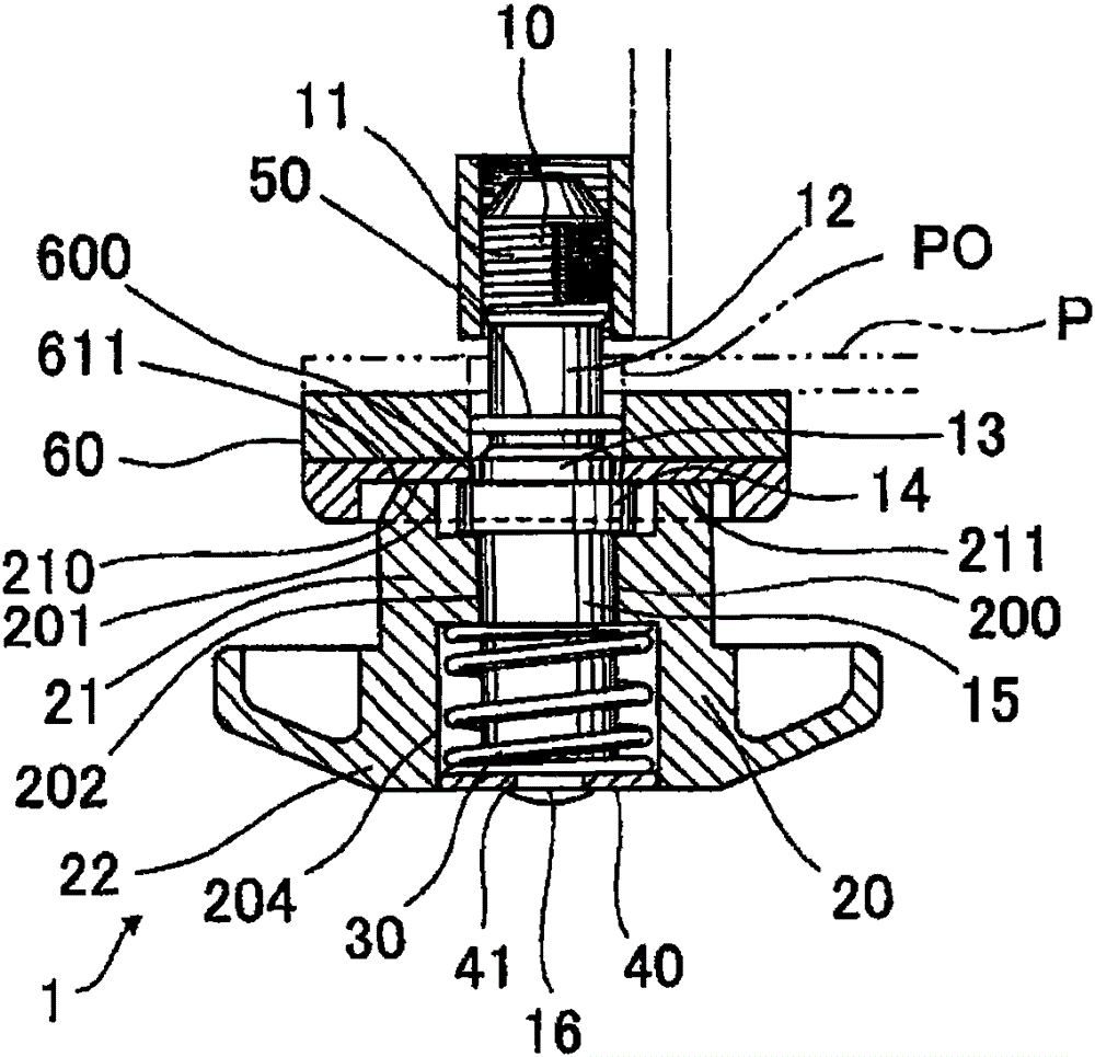
[0070] Next, embodiments of the present invention will be described with reference to the drawings. figure 1 shows the bolt 1 with anti-rotation mechanism. The bolt 1 with anti-rotation mechanism includes: a shaft part 10 having a male thread 11 on the front end side of the shaft part 10; There are teeth 211 on the periphery of the shaft portion 10 and on the joint surface 210 opposite to the periphery of the bolt insertion hole P0 provided on the fastened part P; a spring device 30 that faces the head 20 toward Press and apply force around the bolt insertion hole P0 of the fastened part P; around the hole P0 and has teeth 611 capable of meshing with the teeth 211 of the head 20 .

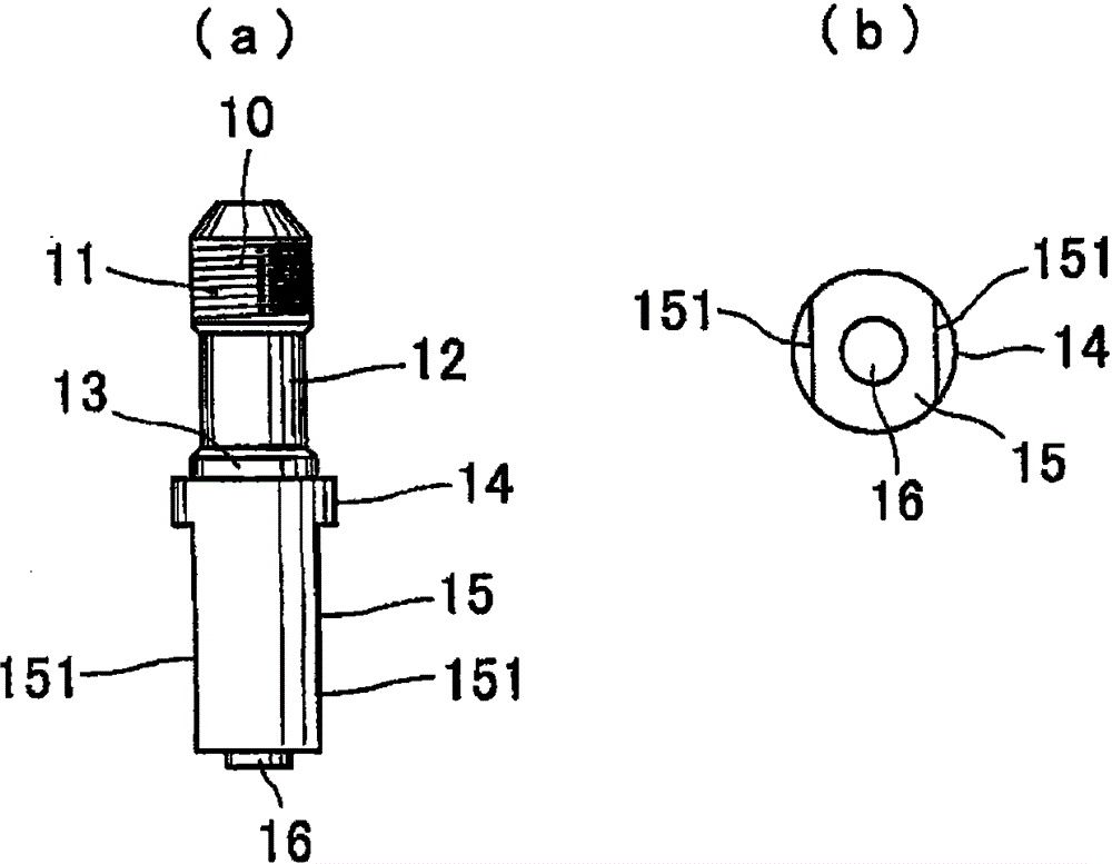
[0071] figure 2 The middle indicates the shaft portion 10 . Such as figure 2 As shown, the shaft portion 10 is made of metal materials such as stainless steel, and has an approximate cylindrical shape as a whole. A male thread 11 is formed on the front end side of its outer peripheral surfac...


PUM


Abstract

PROBLEM TO BE SOLVED: To provide a bolt hard to loosen having stable fastening force for a long time. SOLUTION: The bolt 1 includes a shaft 10 provided with a male screw 11 on the front end side, a head 20 provided on the base end side of the shaft 10 so as to be axially slidable on the shaft 10 and as to be rotatable together with the shaft 10 and provided with teeth 211 on a head seat surface 210, a spring 30 for pressing the head 20 toward a member P to be fastened and a whirl-stop base 60 installed in and fixed to the member P and provided with a plurality of teeth 611. The shaft 10 to be screwed is locked by press-engaging each tooth 211 of the surface 210 with each tooth 611 of the base 60. COPYRIGHT: (C)2012,JPO&INPIT

Description

technical field [0001] The present invention relates to a bolt with an anti-rotation mechanism, in particular to a bolt with an anti-rotation mechanism for detachably fixing components on various machines subject to severe impact or vibration. Background technique [0002] When components are fastened to various machines using bolts and nuts, the bolts may loosen due to vibration of the machine. Therefore, in order to prevent such bolts from loosening, various measures have been taken so far. Generally, a spring washer is installed between the joint surface of the bolt or nut and the fastening surface of the machine, so that a supporting force is always generated between the supporting surface of the bolt or nut and the fastening surface, thereby preventing the bolt from loosening; The tightened nuts are superimposed on the bolts and the nuts are tightened to prevent loosening, and the bolts do not loosen due to the mutual tightening of the so-called double nuts. This tech...

Claims


Application Information

Patent Timeline
Patent Type & Authority Patents(China)
IPC IPC(8): F16B39/22F16B35/00
CPCF16B35/041F16B39/028F16B39/282F16B39/32F16B39/38
Inventor 濑川志朗
Owner TAKIGEN MFG CO LTD
Why Eureka
Try Eureka