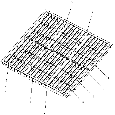
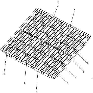
Overlap joint type structured airflow guide floor board
An airflow guiding and flooring technology, which is applied in the field of flooring, can solve the problems of increasing operating costs, reducing the ventilation area of ventilation floors, and increasing energy consumption of refrigeration equipment, and achieves the goal of reducing production costs, increasing matching applicability, and uniform distribution of air supply pressure Effect
Active Publication Date: 2012-10-03
SHANGHAI HUA YU ELECTRON ENG
View PDF6 Cites 3 Cited by
- Summary
- Abstract
- Description
- Claims
- Application Information
AI Technical Summary
Problems solved by technology
Therefore, in the application of the computer room, only the ventilated floor with a lower opening ratio can be used to ensure the load-bearing requirements of the computer room, which greatly reduces the ventilation area of the ventilated floor, resulting in an increase in the energy consumption of the refrigeration equipment and the increase in operating costs
Method used
View moreImage
Smart ImageViewing Examples
Examples
Embodiment Construction
Login to View More PUM
 Abstract
The invention discloses an overlap joint type structured airflow guide floor board, which comprises a first transverse beam, a second transverse beam, a first longitudinal beam, a second longitudinal beam, a third longitudinal beam, a fourth longitudinal beam, a panel, a first grating and a second grating, wherein the first transverse beam and the second transverse beam are parallel to each other; the first longitudinal beam, the second longitudinal beam, the third longitudinal beam and the fourth longitudinal beam are parallel to each other; the first transverse beam, the second transverse beam, the first longitudinal beam, the second longitudinal beam, the third longitudinal beam and the fourth longitudinal beam are vertically staggered; the panel is above the fourth longitudinal beam; and the first grating and the second grating are among the first transverse beam, the second transverse beam, the first longitudinal beam, the second longitudinal beam, the third longitudinal beam and the fourth longitudinal beam. According to the invention, by adopting the overlap joint type structure, the current problem that the opening rate and bearing contradict with each other is solved; and bearing also satisfies requirement of machine rooms in the event of increasing the opening rate.
Description
technical field [0001] The invention relates to a floor, in particular to an airflow guide floor with an overlapping structure. Background technique [0002] The computer room usually adopts the form of under-floor air supply to supply air and cool the servers and equipment in the computer room. The vents of the ventilation floor are generally set flush with the static floor, and the floor needs to be elevated. , The cold air enters the computer room through the vents on the ventilated floor, exchanges heat with the heat generated by the servers and equipment, and then is discharged from the air outlet on the upper part of the computer room. At present, the ventilated floor on the market is generally made of steel plate after stretching, punching, spot welding, and plastic spraying. The inner cavity is hollow to place the grid, and the surface is pasted with HPL melamine anti-static veneer or PVC anti-static veneer. The opening rate is generally small. , while not consider...
Claims
Login to View More Application Information
Patent Timeline
 Patent Type & Authority Applications(China)
IPC IPC(8): E04F15/02F24F13/068
Inventor 孙杰莫儒明
Owner SHANGHAI HUA YU ELECTRON ENG
- R&D Engineer
- R&D Manager
- IP Professional
- Industry Leading Data Capabilities
- Powerful AI technology
- Patent DNA Extraction
Learn More Browse by: Latest US Patents, China's latest patents, Technical Efficacy Thesaurus, Application Domain, Technology Topic, Popular Technical Reports.
© 2024 PatSnap. All rights reserved.Legal|Privacy policy|Modern Slavery Act Transparency Statement|Sitemap|About US| Contact US: help@patsnap.com


