Yarn conveying device on knitting machine

A yarn feeding device and knitting machine technology, applied in knitting, weft knitting, warp knitting, etc., can solve problems such as yarn fluffing, yarn clearer grooves, affecting the quality of knitting machine fabrics, etc., to achieve constant tension, The effect of improving quality and novel structure

Active Publication Date: 2014-06-04
CIXI SUN TEXTILE SCI & TECH
View PDF7 Cites 0 Cited by
  • Summary
  • Abstract
  • Description
  • Claims
  • Application Information

AI Technical Summary

Problems solved by technology

This will definitely make the working yarn deviate from the center of the groove of the yarn clearer and rub against the edge of the groove of the yarn clearer, resulting in yarn fluff and grooves of the yarn clearer, affecting the fabric quality of the knitting machine

Method used


Image

  • Yarn conveying device on knitting machine
  • Yarn conveying device on knitting machine
  • Yarn conveying device on knitting machine

Examples


Embodiment 1

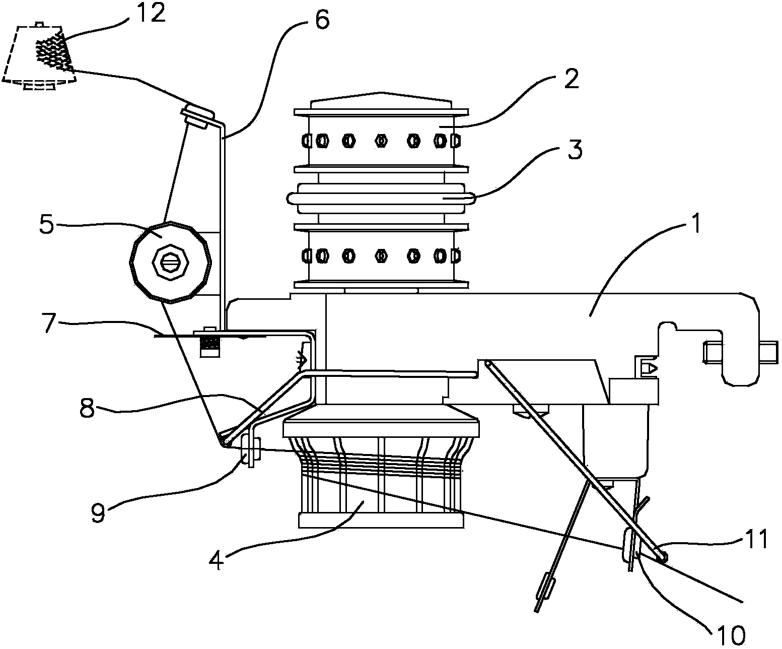
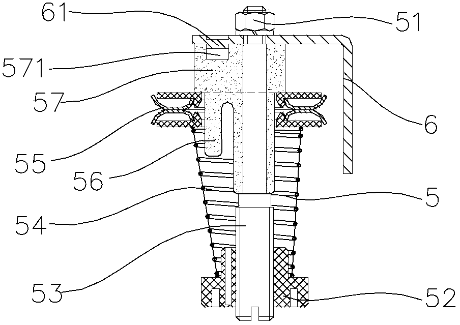
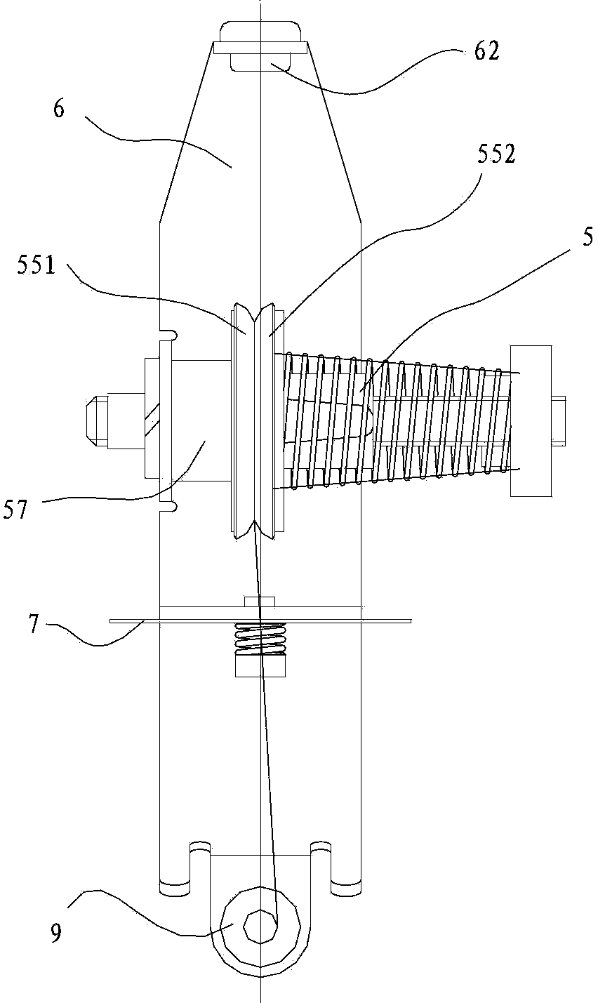
[0020] Such as figure 1 , figure 2 , image 3 and Figure 4 The yarn feeding device on the shown knitting machine includes a housing 1 and a transmission pulley 2, a clutch 3, a wire feeding wheel 4 and a main shaft thereon. The main shaft runs through the housing 1 up and down, the upper part of the main shaft is connected with the transmission pulley 2 and the clutch 3, and the lower part of the main shaft is connected with the transmission pulley 4. Lead frame 6, yarn clamping assembly 5, yarn clearer 7, front detection rod 8, yarn input ceramic ring 9, yarn output ceramic ring 10 and rear detection rod 11 are installed in the shell in sequence from yarn inlet to yarn outlet. On the body 1, the clamping assembly 5 is installed on the housing 1 through the lead frame 6.

[0021] The thread delivery wheel 4 is sequentially provided with a connected yarn introduction area 411, a yarn storage area 421 and a waste silk export area from top to bottom. The yarn introduction ...

Embodiment 2

[0028] Such as figure 1 , figure 2 , image 3 and Figure 5 The structure and data of the yarn feeding device on the knitting machine shown are the same as those in Embodiment 1, the only difference is that the waste silk export body 43 also includes a waste silk transition cylinder 43C, and the waste silk temporary storage cone 43A and the waste silk export cone 43B pass through The waste silk transition cylinder 43C is connected, and the diameter of the waste silk transition cylinder 43C is the same as the diameter of the top of the waste silk export cone 43B.


PUM


Abstract

The invention relates to the field of knitting equipment, in particular to a yarn conveying device on a knitting machine. The yarn conveying device on the knitting machine comprises a casing, and a drive pulley, a clutch, a yarn conveying wheel and a main shaft, which are arranged on the casing; the yarn conveying wheel is provided with a yarn leading-in area, a yarn storing area and a waste yarn leading-out area, which are arranged from the top down in sequence; the yarn leading-in area is provided with an arc surface, which is inclined from the exterior to the interior from the top down; the yarn storing area is provided with a plane surface; the waste yarn leading-out area comprises an upper inclined surface and a lower inclined surface; the upper inclined surface is an inclined plane inclined from the interior to the exterior from the top down; the lower inclined surface is an inclined plane inclined from the exterior to the interior from the top down; and the angle between the upper inclined surface and the yarn storing area is greater than 330 degrees. The yarn conveying device on the knitting machine has the advantages that the structure is novel, residual waste yarns are automatically removed by the yarn conveying wheel, and the tension of conveying yarns by the yarn conveying device on the knitting machine is kept constant, so that the quality of fabric on the knitting machine is improved.

Description

technical field [0001] The invention relates to the field of knitting equipment, in particular to a yarn feeding device on a knitting machine. Background technique [0002] The yarn feeding device on the knitting machine mainly includes a housing, a main shaft, a transmission pulley, a clutch, a wire feeding wheel, a lead frame, a yarn clamping assembly, a yarn clearer, a front detection rod, a yarn inlet ceramic ring, a yarn output ceramic ring and a rear detection rod . The main shaft runs through the housing up and down, its upper part is connected with the transmission pulley and the clutch, and its lower part is connected with the transmission pulley. When working, the transmission belt on the knitting machine drives the transmission pulley on the upper part of the yarn delivery device to rotate, and the clutch and the main shaft rotate to the delivery wheel, so that the delivery wheel rotates, so that the yarn on the yarn tube is pulled out, and the yarn After being ...

Claims


Application Information

Patent Timeline
Patent Type & Authority Patents(China)
IPC IPC(8): D04B15/38D04B27/10
Inventor 高山
Owner CIXI SUN TEXTILE SCI & TECH
Why Eureka
Try Eureka