
Hydraulic jacking system of transporting girder vehicle

A beam transport vehicle and hydraulic technology, which is applied in the direction of parallel load-carrying vehicles, etc., can solve the problems of box girder tilting, poor synchronization performance of hydraulic jacking cylinders, and easy distortion of box girder, so as to achieve the effect of reducing the height of box girder

Active Publication Date: 2012-10-03
徐州徐工能源装备有限公司
View PDF10 Cites 3 Cited by
  • Summary
  • Abstract
  • Description
  • Claims
  • Application Information

AI Technical Summary

Problems solved by technology

[0004] The purpose of the present invention is to provide a hydraulic jacking system for a beam transport vehicle, which solves the problem that the box girder is always supported by four points during the transport process, and the box girder is prone to distortion; and the synchronous performance of the hydraulic jacking cylinder is not good during the lifting process , it is prone to the problem of box girder inclination

Method used


Image

  • Hydraulic jacking system of transporting girder vehicle
  • Hydraulic jacking system of transporting girder vehicle
  • Hydraulic jacking system of transporting girder vehicle

Examples


Embodiment 1

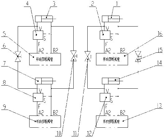
[0014] Embodiment 1: The jacking system includes a first jacking cylinder 1, a first balance valve 2, a second jacking cylinder 3, a second balance valve 4, a first proportional reversing valve 5, a first ball valve 6, a third Jacking cylinder 7, third balance valve 8, second proportional reversing valve 9, second ball valve 10, third ball valve 11, fourth balancing valve 12, third proportional reversing valve 13, fourth jacking cylinder 14, The fourth ball valve 15 and the fourth proportional reversing valve 16, the rod cavity of the second jacking cylinder 3 and the third jacking cylinder 7 are connected with the second ball valve 10 through a hydraulic pipe, the second jacking cylinder 3 and The rodless cavity of the third jacking cylinder 7 is connected with the first ball valve 6 through a hydraulic pipe; the rod cavity end of the second jacking cylinder 3 is connected with one end of the first proportional reversing valve 5, and the second jacking cylinder The rodless ch...


PUM


Abstract

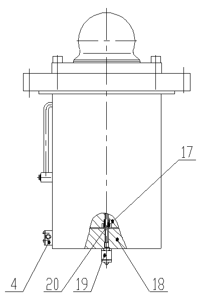
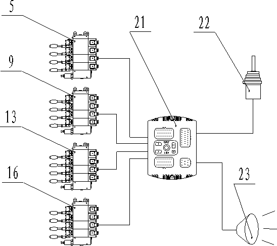
The invention belongs to hydraulic jacking systems, and relates to a hydraulic jacking system of a transporting girder vehicle, which comprises four hydraulic jacking cylinders loaded with displacement sensors, four electrical control proportioning valves, four ball valves, an operating handle, a controller and a warner, wherein the four hydraulic jacking cylinders are divided into two groups, that is, a front group and a rear group; rod chambers of the two hydraulic jacking cylinders in each group are connected by a hydraulic pipeline; one of the ball valves is arranged in the middle of the pipeline; likewise, rodless chambers of the two hydraulic jacking cylinders in the group are connected; when the four ball valves in the front group and the rear group are closed, the hydraulic jacking cylinders form four points for supporting a box girder; when the two ball valves in one group are closed, and the two ball valves in the other group are opened, the hydraulic jacking cylinders form four points acting on the box girder and three points for supporting the box girder so as to ensure that the box girder is not twisted during the lifting and transporting processes; during the process of the lifting of the box girder, the displacement sensors monitor the lifting heights of the cylinders in a real-time manner; and when the lifting speed of the some cylinder is too high, the controller gives out a command to the control valve to a proportional control valve to automatically adjust the lifting speed of the cylinders and further ensure that the box girder is not inclined during the process of lifting.

Description

technical field [0001] The invention relates to a hydraulic jacking system, in particular to a hydraulic jacking system of a beam transport vehicle. Background technique [0002] In the construction of high-speed railways in western my country, the box girder is often transported from the girder yard to the box girder erection site through a tunnel. The top surface interferes with the upper arch of the tunnel, so a hydraulic jacking system is now used to solve this problem. The specific method is: before the box girder is put on the beam transport vehicle, first adjust the jacking oil cylinder to a lower position, and then put the box girder on the jacking oil cylinder for transportation. When the box girder is transported to the construction site, the beam transport vehicle and frame After the bridge machine is docked, raise the jacking cylinder to a certain height, place the beam moving trolley at a proper position under the box girder, then lower the jacking cylinder,...

Claims


Application Information

Patent Timeline
Patent Type & Authority Applications(China)
IPC IPC(8): B60P1/02
Inventor 王增民高成国王伟牛勇
Owner 徐州徐工能源装备有限公司
Learn More