
Locked-rotor protection method for driving motor of electric vehicle

A drive motor and stall protection technology, which is applied to electric vehicles, control drives, electrical devices, etc., can solve the problems of drive motor stall and temperature rise characteristics, and achieve the effect of protecting components

Active Publication Date: 2014-12-10
CHERY AUTOMOBILE CO LTD
View PDF4 Cites 2 Cited by
  • Summary
  • Abstract
  • Description
  • Claims
  • Application Information

AI Technical Summary

Problems solved by technology

[0003] According to the definition of stalling in the national standard, it can be known that the stalling torque is generally the peak torque of the motor, but in the use of electric vehicles, the torque that causes the driving motor to stall is not only the peak torque, but at any point within its torque output range may cause the drive motor to stall
At the same time, when used at different ambient temperatures, the temperature rise characteristics of the drive motor when it is locked are very different.

Method used

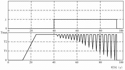
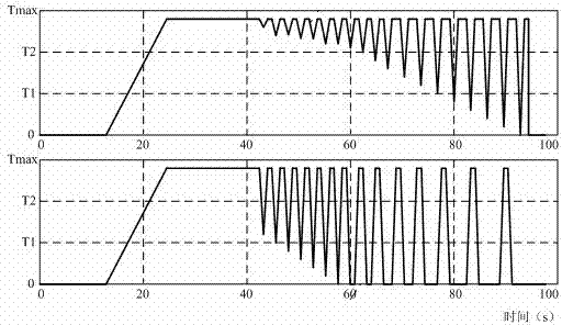

Image

  • Locked-rotor protection method for driving motor of electric vehicle
  • Locked-rotor protection method for driving motor of electric vehicle
  • Locked-rotor protection method for driving motor of electric vehicle

Examples


Embodiment Construction

[0016] Below with reference to the accompanying drawings, through the description of the implementation examples, the specific embodiments of the present invention, such as the shape, structure, mutual position and connection relationship between each part, the role and working principle of each part, etc., will be further described. detailed instructions.

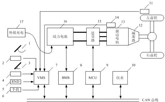
[0017] Such as figure 1 , VMS (vehicle controller) 7 detects the driver's demand for accelerator pedal 3 and brake pedal 1, and analyzes the driver's request for driving or braking torque. The VMS (vehicle controller) 7 can analyze the driver's gear request according to the signal of the gear detector 5, and can calculate the vehicle speed and the speed of the driving motor according to the signals of the speed sensor 11 and the driving motor position sensor 14, and then according to the CAN bus The system receives relevant status information of the power battery 16, etc., and finally calculates the request for driving or...


PUM


Abstract

The invention provides a locked-rotor protection method for a driving motor of an electric vehicle, which covers the full output range of a control torque of the driving motor. The method comprises the following steps of: dividing the control torque of the driving motor into N regions from 0 to the largest control torque according to a rotating speed signal of the driving motor and a control torque signal of a whole vehicle controller to the driving motor; setting a locked-rotor judging condition for each region and judging whether the driving motor enters into a locked-rotor state or not; if so, intervening the control torque of the driving motor by the whole vehicle controller, wherein an intervening quitting condition of the whole vehicle controller is that a rotating speed of the driving motor is more than a set rotating speed threshold value of a motor locked-rotor state. The locked-rotor protection method covers the condition that the locked-rotor may happen in the full output range of the control torque of the driving motor so as to ensure the driving motor not to be damaged by locked rotor.

Description

technical field [0001] The invention relates to the technical field of motor control of electric vehicles, and specifically designs a method for protecting a drive motor of an electric vehicle from stalling. Background technique [0002] In the actual use of traditional internal combustion engine vehicles, the phenomenon of engine flameout often occurs, mainly because the handbrake is not released in time when starting, the clutch is not stepped on in time when braking, and the brake is loosened too early when starting on a slope. Electric vehicles will also have the phenomenon that the driving motor is suffocated under the above circumstances, which is generally called motor stalling. In the national standard GB / T 18488.2-2006, the experimental method of motor stall is described in detail. When the motor is locked, the power factor is low, the locked rotor current rises rapidly, and the temperature of the inverter also rises rapidly. If it takes a long time, the driving m...

Claims


Application Information

Patent Timeline
Patent Type & Authority Patents(China)
IPC IPC(8): B60L3/00B60L15/00
Inventor 刘小飞
Owner CHERY AUTOMOBILE CO LTD
Learn More