Cutting device and clamping device thereof

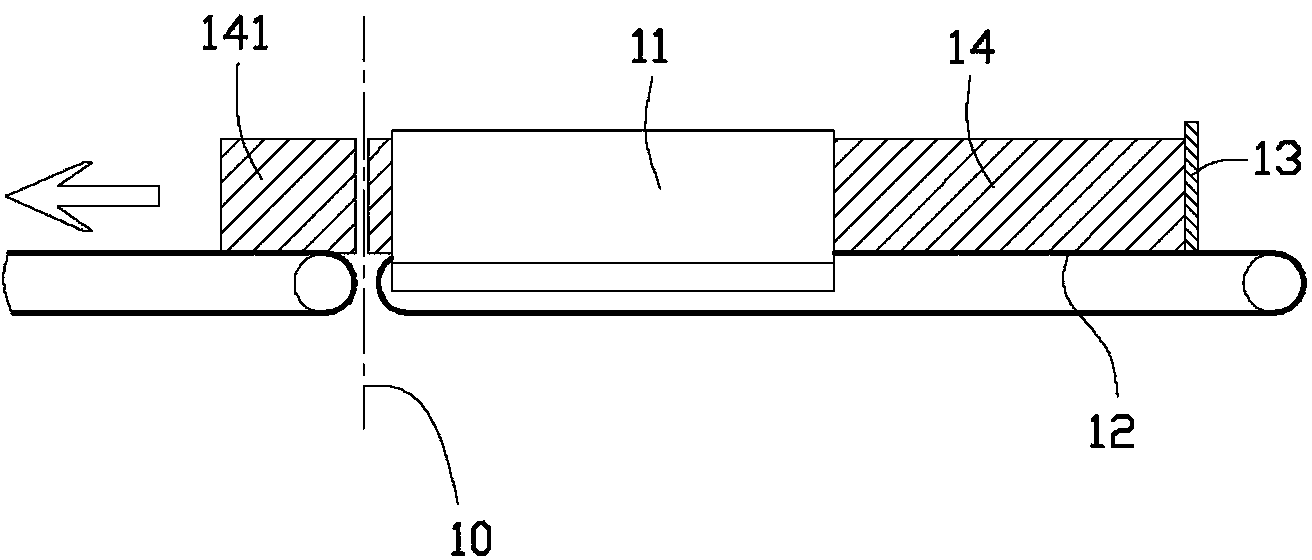
A technology of clamping device and cutting equipment, applied in the direction of metal processing, etc., can solve the problems of affecting the quality of finished products, the length of the roll paper 141 is different, and the size cannot be changed, so as to achieve the effect of improving quality

Active Publication Date: 2015-02-11
海南金红叶纸业有限公司 +1
View PDF7 Cites 0 Cited by
  • Summary
  • Abstract
  • Description
  • Claims
  • Application Information

AI Technical Summary

Problems solved by technology

[0004] The above-mentioned cutting equipment has the following defects: since the size of the holding space 17 of the pinch tube 11 is fixed by the screw 16, the size cannot be changed. If the diameter of the long paper roll 14 is slightly different, there will be a phenomenon that it cannot be tightened or clamped badly.
And if the diameter of the long paper roll 14 is slightly larger than the size of the storage space 17, the long paper roll 14 will be blocked by the pinch tube 11 when it runs towards the blade 10 and cannot run a predetermined distance forward smoothly, so that the cut web will 141 There is a phenomenon of different lengths, which affects the quality of the finished product
In addition, because the long paper roll 14 is relatively soft, if the long paper roll 14 is caught by the pinch tube 11, it usually arches and breaks the push plate 13, causing the equipment to fail and need to be shut down for maintenance, affecting production efficiency

Method used


Image

  • Cutting device and clamping device thereof
  • Cutting device and clamping device thereof
  • Cutting device and clamping device thereof

Examples


Embodiment Construction

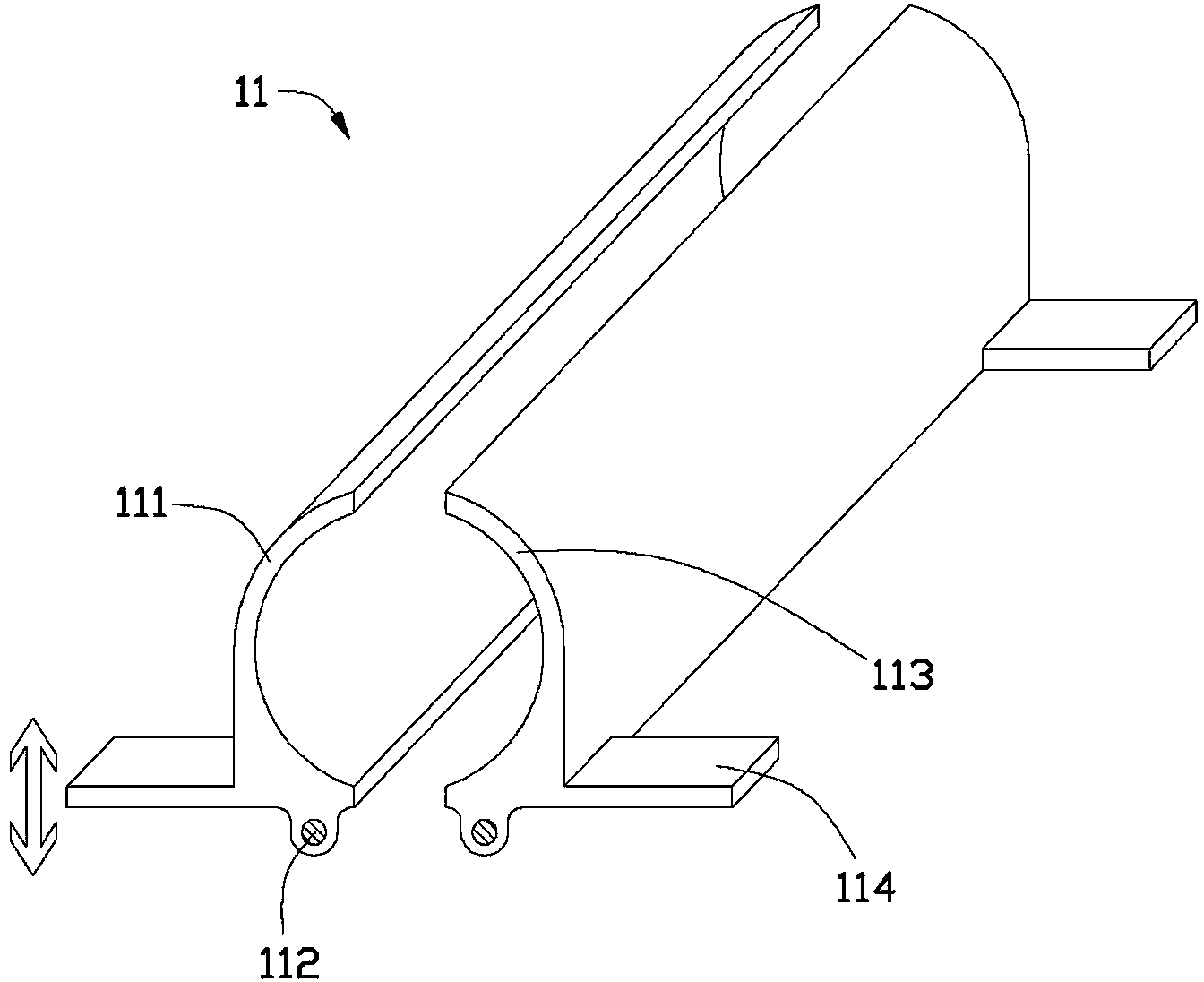
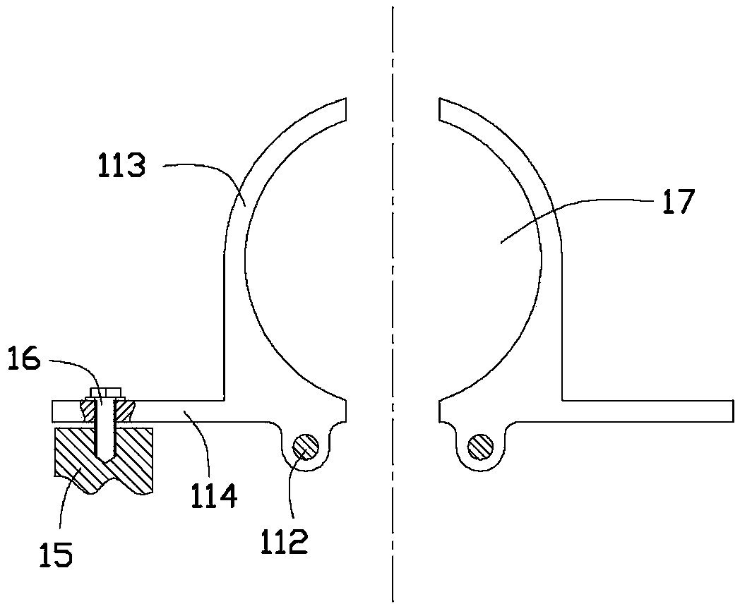
[0021] Please refer to Figure 4 , The clamping device provided by the first embodiment of the present invention includes two clamping arms 30 and two pivots 36 , and the clamping arms 30 are rotatably connected to the pivots 36 .

[0022] The clamping device is used in cutting equipment. When the cutting device cuts materials, the clamping device is used to clamp the materials so as to facilitate the completion of the cutting action. The cutting equipment also includes a frame, a conveyor belt, a push plate and a cutter. The push plate is fixed on the conveyor belt, the conveyor belt and the push plate are used to transfer the material to be cut, the cutter is used to cut the material, and the cutter and the conveyor belt are connected with the frame of the cutting device. The push plate is used to assist the conveyor belt to pass the material to be cut. Therefore, in some embodiments, if the conveyor belt has sufficient transmission force, there is no need to set a push p...


PUM


Abstract

The invention discloses a clamping device assembled in a cutting device for clamping a material to be cut. The clamping device comprises two clamping arms, two pivot shafts, a drive element and a control valve for controlling the drive element, wherein each clamping arm comprises a fixing section, a pivot section and a clamping section; the pivot section is rotationally connected to the pivot shaft; the clamping section is used for clamping and fixing the material; the drive element is connected with the fixing sections of the clamping arms; and the control valve controls the drive element to periodically move in a reciprocating manner, so that the clamping arms periodically rotate around the pivot shafts in the reciprocating manner. The invention also provides the cutting device with the clamping device; and the cutting device can be used for cutting the material such as reel-shaped toilet paper and the like. By the cutting device disclosed by the invention, the clamping arms can release the material by actuating the drive element when the materials transferred, so the phenomenon that the materials are clamped between the clamping arms due to size fluctuation of the material is avoided. The drive element controls the clamping arms to clamp the material when the materials are cut, so that size precision of cutting can be prevented from being affected by material loosening during cutting, and further, the quality of the product can be improved.

Description

technical field [0001] The invention relates to a cutting device, in particular to a cutting device for cutting paper rolls and a clamping device thereof. Background technique [0002] Roll toilet paper is a common daily necessities. The roll type toilet paper is usually formed by cutting the paper roll after rewinding the toilet paper with a wider paper width (for example, 2-3 meters) into a paper roll with a predetermined diameter. Wherein the cutting of the paper roll is realized by the paper roll cutting equipment. Such as figure 1 As shown, an existing cutting device includes a blade 10 , a pinch tube 11 , a conveyor belt 12 and a push plate 13 . The push plate 13 is fixedly connected with the conveyor belt 12 and is used to push the long paper roll 14 to be cut placed on the conveyor belt 12 . The clamp tube 11 is used to fix the long paper roll 14 at a predetermined position to facilitate cutting. The push plate 13 and the conveyor belt 12 move in a gap. After t...

Claims


Application Information

Patent Timeline
Patent Type & Authority Patents(China)
IPC IPC(8): B26D7/02
Inventor 吴月明冯丽东郭淳钱丽丽
Owner 海南金红叶纸业有限公司
Why Eureka
Try Eureka