
Pulse signal test device of inertial platform for launch vehicle

A pulse signal and inertial platform technology, which is applied in the direction of monitoring the pulse chain mode, can solve the problem of system error increase, and achieve the effect of avoiding real-time errors, avoiding unification, and avoiding further deterioration of real-time performance

Inactive Publication Date: 2012-09-26
蔡远文
View PDF4 Cites 7 Cited by
  • Summary
  • Abstract
  • Description
  • Claims
  • Application Information

AI Technical Summary

Problems solved by technology

In addition, channel expansion in this way is equivalent to adding more channels to a counter card, so when the computer reads the count values ​​of each channel one by one, it takes more time, so the system error will further increase

Method used


Image

  • Pulse signal test device of inertial platform for launch vehicle
  • Pulse signal test device of inertial platform for launch vehicle
  • Pulse signal test device of inertial platform for launch vehicle

Examples


Embodiment Construction

[0014] The specific embodiment of the present invention is described in detail below in conjunction with accompanying drawing:

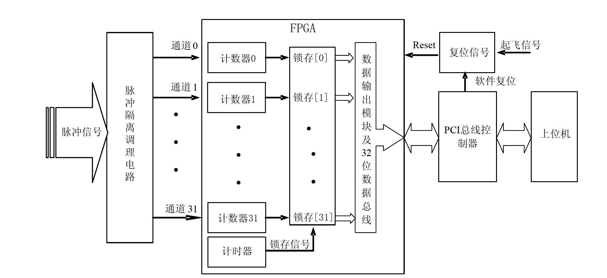
[0015] refer to figure 1 As shown, the pulse signal test device of the launch vehicle inertial platform of this embodiment includes a pulse isolation and conditioning board with an expansion slot, an FPGA model of A3P 600, a PCI bus controller of model PLX9054, and a host computer. Among them, there are 32 channels of independent pulse isolation conditioning circuits on the pulse isolation conditioning board with expansion slots, and each channel of pulse isolation conditioning circuits is used to electrically isolate the corresponding input pulse signals, and then conditioning and converting them into 0-5V Digital logic level; each counter set in the FPGA is used to independently count the digital logic level of the corresponding input channel, and simultaneously latch its own counting data at a set time interval (for example, 40ms, which can be adj...


PUM


Abstract

The invention discloses a pulse signal test device of an inertial platform for a launch vehicle. The pulse signal test device comprises a pulse isolation conditioning board, FPGA (field programmable gata array), a PCI (programmable communication interface) bus controller and an upper computer, wherein the pulse isolation conditioning board is provided with an expansion slot; a multi-channel pulse insulation conditioning circuit is arranged on the pulse isolation conditioning board; each counter is arranged in the FPGA and is used for independently counting the digital logic level of the corresponding input channels and locking the self enumeration data to a latch corresponding to the input channel through the pre-set time interval; a handshake mode is adopted to communicate the PCI bus controller and the FPGA; the data bus of the FPGA is used for reading the current stored data of each latch to the self FIFO (first-in-first-out) in parallel; and the upper computer is used for obtaining data from the FIFO of the PCI bus controller according to the method of a cPCI bus protocol. The pulse signal test device of the inertial platform for the launch vehicle has good expansibility and instantaneity.

Description

technical field [0001] The invention relates to a pulse signal testing technology, in particular to a pulse signal testing device for an inertial platform of a carrier rocket. Background technique [0002] The rocket attitude signal output by the inertial platform of the launch vehicle is usually a pulse signal, which needs to be counted and collected in order to analyze and track the rocket attitude. At present, for the acquisition of pulse signals of rocket inertial platforms, general-purpose counting boards are often used, such as the cPCI-8554 multi-function counting / timer card of ADLINK Technology Co., Ltd., and the PXI-6602, PXI-6608, PXI- 6624 card, CPI-2390 optical isolation counter card of Altai Technology Development Co., Ltd., etc. The basic principles of the above-mentioned counter cards are the same: set the time interval for the computer to read data through software settings, and the calculation of the time interval is completed by the timer on the counter bo...

Claims


Application Information

Patent Timeline
IPC IPC(8): H03K5/19
Inventor 蔡远文姚静波辛朝军程龙李岩解维奇张宇王华
Owner 蔡远文
Learn More