
Device and method for detecting position degree of valve guide pipe holes of cylinder cover of engine

An engine cylinder head and valve guide technology, which is applied to mechanical measuring devices, measuring devices, and mechanical devices, etc., can solve the problem of not being able to ensure that the cumulative error of multiple guide holes can meet the precise position of the installed valve guide rod and the large deviation of the guide hole position. , the poor sealing performance of the guide rod valve, etc., to achieve the effect of simple structure, convenient operation and reducing cumulative error

Active Publication Date: 2012-09-26
WUHU YONGYU AUTOCAR INDAL
View PDF5 Cites 17 Cited by
  • Summary
  • Abstract
  • Description
  • Claims
  • Application Information

AI Technical Summary

Problems solved by technology

[0002] At present, in the machining of the cylinder head of an automobile engine, there are many valve guide holes (there are more double camshaft cylinder heads), and various errors during machining will cause a large deviation in the position of individual guide holes, resulting in the assembly of valves on the cylinder head. The position accuracy of the guide rod is too low, and even some guide rods have poor valve sealing due to errors and affect the efficiency of the internal combustion engine, so it is necessary to detect the position of the guide rod hole
According to the traditional cylinder head valve guide hole position detection method, only the position degree of a single guide hole is detected, and it cannot guarantee whether the cumulative error generated during the detection between multiple guide holes meets the requirements for the precise position of the installed valve guide rod, so How to reduce this cumulative error is a big problem

Method used


Image

  • Device and method for detecting position degree of valve guide pipe holes of cylinder cover of engine
  • Device and method for detecting position degree of valve guide pipe holes of cylinder cover of engine
  • Device and method for detecting position degree of valve guide pipe holes of cylinder cover of engine

Examples


Embodiment Construction

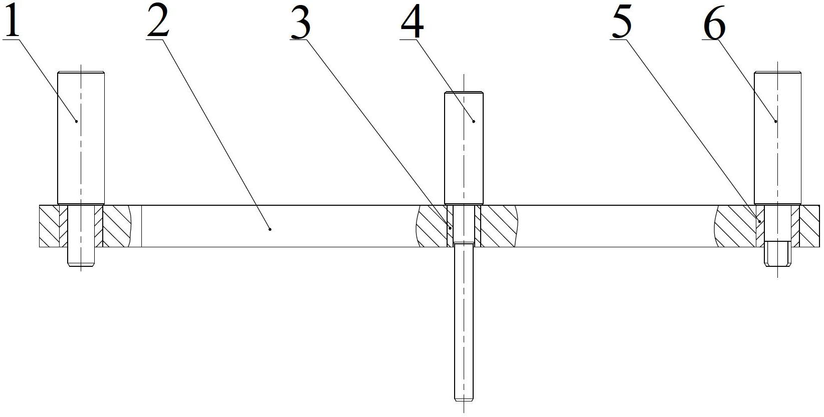
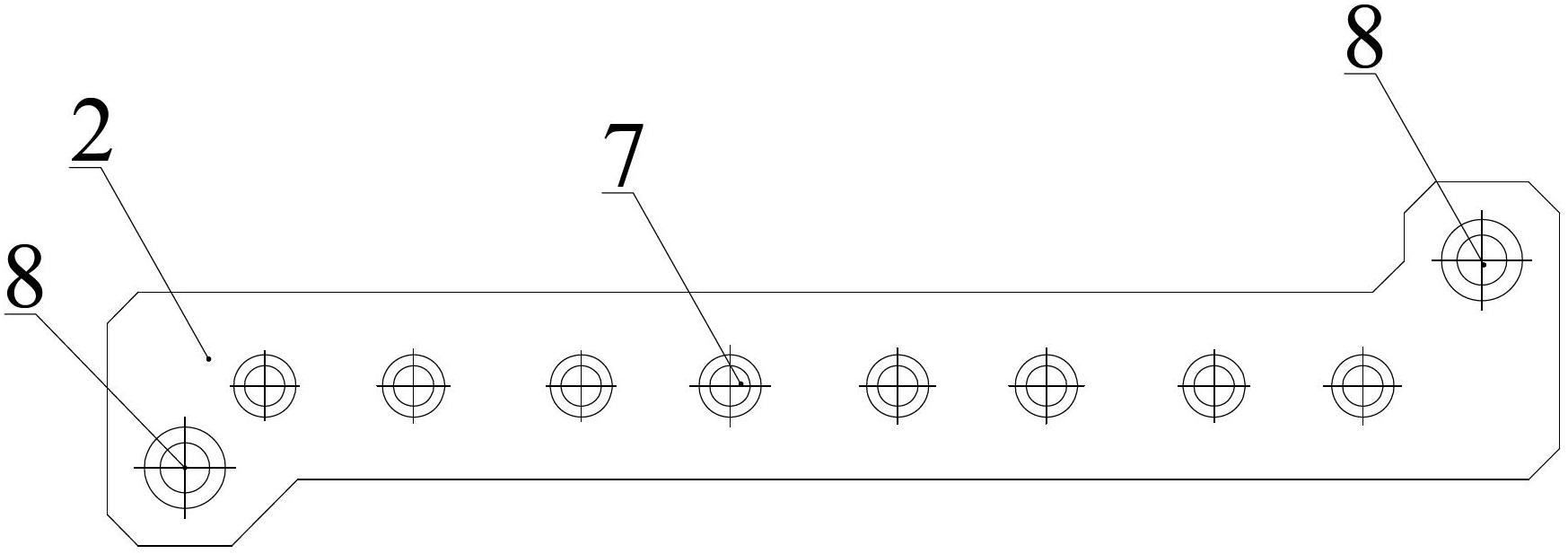
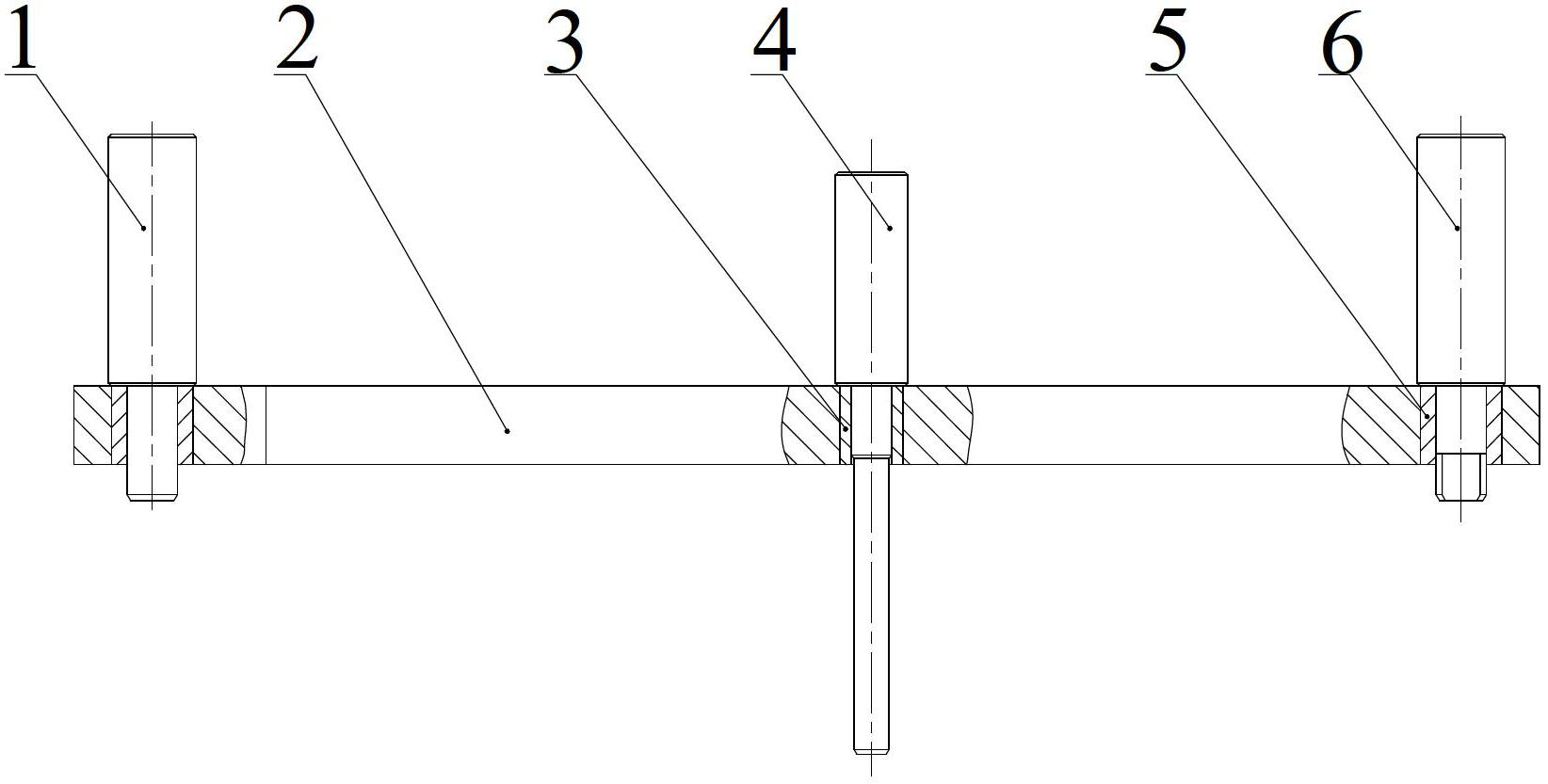
[0014] The invention relates to an engine cylinder head valve guide hole position detection device, which includes a special detection mandrel 4 which is the same as that used in the prior art. In order to solve the problems existing in the prior art, such as figure 1 and figure 2 As shown, the detection device also includes a detection template 2, the detection template 2 is a long plate shape, and the detection template 2 is provided with the same number and position alignment as the valve guide holes on the cylinder head for the insertion of the detection mandrel 4. For the detection hole 7, during detection, the detection template 2 is positioned on the bottom surface of the cylinder head by a positioning mechanism. During detection, the cylinder head is placed upside down on the detection platform, and the bottom surface of the cylinder head is set upward. Compared with the prior art, the detection device is simple in structure and easy to operate. It only needs to inse...


PUM


Abstract

The invention discloses a device for detecting the position degree of valve guide pipe holes of a cylinder cover of an engine. The device comprises a detection mandrel and a detection template, wherein detection holes of which the quantity is the same as that of the valve guide pipe holes on the cylinder cover and which are aligned with the valve guide pipe holes on the cylinder cover and are used for inserting the detection mandrel are formed in the detection template; and the detection template is positioned on the bottom surface of the cylinder cover through a positioning mechanism during detection. Compared with the prior art, the invention has the advantages that the device has a simple structure and is convenient to operate; unqualified hole positions can be quickly and simply detected by the device; compared with the traditional detection method, the method has the advantages that the detection accuracy is high, the accumulated error generated during detection is reduced, and the detection efficiency is also high; and in addition, by the detection method for the device, the process is simple, the method can be conveniently and efficiently operated, employees who detect products can operate the device without training, and the detection efficiency is high.

Description

technical field [0001] The invention relates to a detection device, in particular, the invention relates to a detection device and a detection method for the position degree of an engine cylinder head valve guide hole. Background technique [0002] At present, in the machining of the cylinder head of an automobile engine, there are many valve guide holes (there are more double camshaft cylinder heads), and various errors during machining will cause a large deviation in the position of individual guide holes, resulting in the assembly of valves on the cylinder head. The position accuracy of the guide rod is too low, and even some guide rods have poor valve sealing due to errors and affect the efficiency of the internal combustion engine. Therefore, it is necessary to detect the position of the guide rod hole. According to the traditional cylinder head valve guide hole position detection method, only the position degree of a single guide hole is detected, and it cannot guarant...

Claims


Application Information

Patent Timeline
IPC IPC(8): G01B5/00
Inventor 郑志勋
Owner WUHU YONGYU AUTOCAR INDAL
Learn More