
Method for manufacturing organic electroluminescent element

An electroluminescent, electromechanical technology, applied in the field of producing organic electroluminescent devices, to achieve the effect of suppressing total reflection

Inactive Publication Date: 2015-05-06
SUMITOMO CHEM CO LTD +1
View PDF4 Cites 0 Cited by
  • Summary
  • Abstract
  • Description
  • Claims
  • Application Information

AI Technical Summary

Problems solved by technology

Therefore, most of the light emitted by the emissive layer does not pass out and is therefore ineffectively used in the current situation

Method used


Image

  • Method for manufacturing organic electroluminescent element
  • Method for manufacturing organic electroluminescent element
  • Method for manufacturing organic electroluminescent element

Examples


Embodiment

[0156]

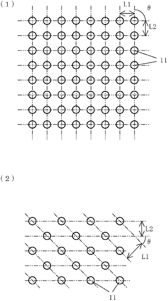
[0157] Using an electron beam (EB) lithography equipment, patterning is performed on the part made of Si to form a plurality of periodic two-dimensional cylinders to prepare the model 12 made of Si. Figure 4 It is a diagram schematically showing the model. Figure 4 (1) The top view of the model is shown schematically, and Figure 4 (2) A cross-sectional view of the model is schematically shown. The size of the model in plan view is 20mm×20mm, and has a patterned structure of a plurality of cylinders in its central part. The area having the structure with a plurality of patterned cylinders has a size of 10 mm×10 mm in the center of the model in plan view. The dimensions of each cylinder are: the diameter Lb is 150 nm and the height Ld is 160 nm. The distance La between the central axes of adjacent cylinders is 300 nm. In addition, the angle θ between the vertical bar and the horizontal bar represented by the chain-shaped double dashed line is 60°. The interval Lc...


PUM


Abstract

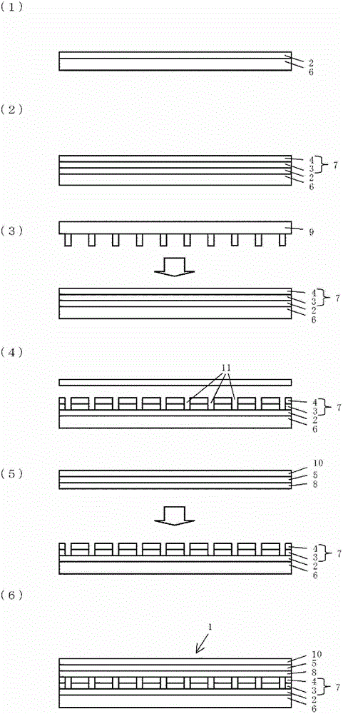
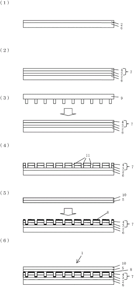
Disclosed is a method for manufacturing an organic electroluminescent (EL) element which is provided with a pair of electrodes and two or more organic layers disposed between the electrodes, and which includes light-emitting layers as the two or more organic layers. The manufacturing method for an organic EL element includes: a step for forming one electrode of the pair of electrodes; a step for forming the two or more organic layers which have a periodic structure wherein the propagation direction of light propagating in a direction substantially perpendicular to the thickness direction of the light-emitting layers is inclined in said thickness direction; and a step for forming the other electrode of the pair of electrodes. In the step for forming the two or more organic layers, two or more planar layers constituting the organic layers are laminated, and the periodic structure which is periodically arranged in two dimensions is then formed on the two or more planar layers by means of an imprinting method in the plane perpendicular to the thickness direction of the light-emitting layers.

Description

Technical field [0001] The present invention relates to a method of producing an organic electroluminescence device (hereinafter also referred to as an organic EL device), and to a display device and a lighting device including the organic EL device obtained by this method. Background technique [0002] The organic EL device includes a pair of electrodes (anode and cathode) and a light-emitting layer between the electrodes. When a voltage is applied to the pair of electrodes, injection of holes from the anode and injection of electrons from the cathode occur, and these holes and electrons are combined with each other in the light-emitting layer, thereby causing the organic EL device to emit light. [0003] One of the pair of electrodes is composed of an optically transparent electrode. The light generated in the light-emitting layer passes through the optically transparent electrode outward. At present, indium tin oxide (abbreviated as ITO) films are often used in such optically ...

Claims


Application Information

Patent Timeline
Patent Type & Authority Patents(China)
IPC IPC(8): H05B33/10H01L51/50
CPCH10K71/20H10K71/50H10K50/11H10K71/821H10K71/00H10K59/879H10K50/858
Inventor 山本恭子贾勒特·迪蒙罗洪义
Owner SUMITOMO CHEM CO LTD
Learn More