
Wide-area reactive optimal running method for power distribution network

A technology for optimizing operation and distribution network, applied in reactive power compensation, reactive power adjustment/elimination/compensation, etc. sufficiency

Active Publication Date: 2012-09-19
曲靖皓丰工贸有限公司
View PDF3 Cites 18 Cited by
  • Summary
  • Abstract
  • Description
  • Claims
  • Application Information

AI Technical Summary

Problems solved by technology

The main disadvantage of the current switching method of reactive power compensation devices in the distribution network is that it can only automatically switch the compensation capacity of the compensation capacitor according to the reactive power load balance of each distribution transformer, and only realize the partial area of ​​each distribution transformer and the following power grid. The reactive power balance of the distribution network cannot control the switching of reactive power compensation capacity from the overall situation of the reactive power load of the distribution network
Since the variation rules of distribution transformer loads (including reactive loads) in the distribution network are not the same, the current method of switching reactive power compensation devices in the distribution network does not fully utilize the compensation capacitors, and it is difficult to ensure the overall no-power load of the distribution network. power balance, thereby affecting the high-quality economic operation of the distribution network

Method used


Image

  • Wide-area reactive optimal running method for power distribution network
  • Wide-area reactive optimal running method for power distribution network
  • Wide-area reactive optimal running method for power distribution network

Examples


Embodiment

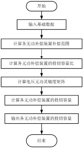
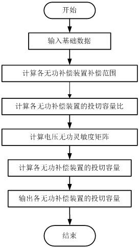
[0067] Such as figure 1 , 2 As shown, the specific steps of a wide-area reactive power optimization operation method for a certain 10kV distribution network are as follows:

[0068] (1) Input basic data

[0069] first enter figure 2 The basic data of a certain 10kV distribution network shown (including the basic data of each node, that is, the node number, the voltage level of the node, the upper limit of the node voltage, the lower limit line of the node; the basic data of each line, that is, the number of the first and last nodes of the line, the resistance R l ,Reactance X l , Density B l , rated voltage U Bl ; The basic data of each distribution transformer, that is, the load number of the distribution transformer, the node numbers on both sides, the resistance R T ,Reactance X T , conductance G m , Density B m , Ratio k T ,Rated Capacity S NT , High voltage side rated voltage U Bl1 , Low voltage side rated voltage U Bl2 ). The basic data of e...


PUM


Abstract

The invention relates to a wide-area reactive optimal running method for a power distribution network and belongs to the technical field of reactive compensation of the power distribution network of a power system. The method comprises the following steps: utilizing a computer and a program to input the basic data of the power distribution network and each reactive compensation device of the power distribution network; calculating a compensation scope and a prior level of each reactive compensation device; calculating a switching capacity of each reactive compensation device according to the compensation scope of each reactive compensation device and real-time measuring information of a root node and each compensation node of the power distribution network; and controlling each capacitor to switch. According to the method provided by the invention, the voltage reactive running condition of the whole power distribution network is fully considered; the use ratio of the compensation device is greatly increased; the power loss and voltage loss of the power distribution network are reduced; the voltage quality of the power distribution network is increased; the running of the electric equipment under a rated condition is ensured; and the social and economic benefits are obvious. The wide-area reactive optimal running method is widely applied to the voltage reactive optimal running and control of the power distribution network of the power system.

Description

Technical field [0001] The invention is the field of non -contribution compensation technology for power system distribution grids, which specifically involves optimized operation methods for power system distribution grids. Background technique [0002] The distribution network is an important link between the power system and the user. It has a large coverage area and a large number of equipment. It is an important part of the power system.Improving the voltage quality of the distribution network and reducing the operational loss of the distribution network is of great significance for improving the quality of power supply and ensuring the high -quality economic operation of the power system.Revitalizing compensation is one of the effective measures to improve the voltage quality of the distribution network and reduce the operational loss of the distribution network. [0003] The power -free optimization operation of the transmission grid is usually based on the trendy equation...

Claims


Application Information

Patent Timeline
Patent Type & Authority Applications(China)
IPC IPC(8): H02J3/18
CPCY02E40/30
Inventor 赵霞赵科余娟颜伟杜兵胡浩谢伟赖杰
Owner 曲靖皓丰工贸有限公司
Learn More