


Quick Research
Generate reliable direction feasibility study reports for your R&D in just a few steps.

Technical Q&A
Discover and master advanced knowledge NOW. Basics, ideas, possibilities, all at once.

Find Solutions
As an expert in R&D theories, this can generate solutions to your technical problems instantly.

Evaluate Feasibility
Analyze your overall solution with one click, know your potential R&D risks in advance.

Monitor Landscape
Get weekly tech updates, stay abreast of the latest tech innovations and key insights.
Device for adjusting curvature radius of cylindrical mirror
A technology of cylindrical mirror and surface mirror, which is applied in the field of lasers, can solve the problems of reduced laser energy conversion efficiency, increased laser loss, difficult laser device adoption, etc., to achieve the effects of avoiding laser damage, maintaining stable operation, and easy assembly
- Summary
- Abstract
- Description
- Claims
- Application Information
AI Technical Summary
Problems solved by technology
Method used
Image

Examples
Embodiment 1
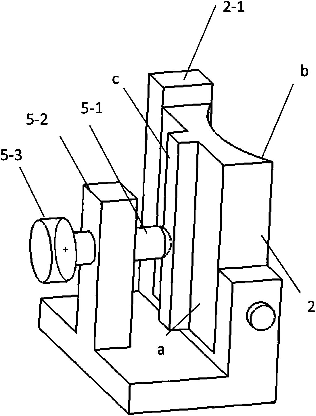
[0046] Such as figure 1 As shown, one end of the ejector rod 5-1 connected to the ejector rod drive unit 5-3 is provided with an external thread, and the ejector rod drive unit 5-3 is provided with an internal thread matching the external thread, and the ejector rod drive unit 5-3 is rotated It can promote telescopic movement of the push rod 5-1 in the horizontal direction. The ejector rod 5-1 of this embodiment runs through the ejector rod support 5-2, and the ejector rod 5-1 and the ejector rod support 5-2 are connected by threads.
[0047] In this embodiment, the purpose of changing the radius of curvature R of the cylindrical mirror 2 is to change the force exerted by the ejector rod 5-1 on the outer surface a of the cylindrical mirror 2 by rotating the ejector rod driving unit 5-3. Such as figure 1 As shown, the minimum value of the change value Δx of the radius of curvature Δx of the cylindrical mirror 2 can be realized by manually adjusting the ejector rod drive unit ...
Embodiment 2
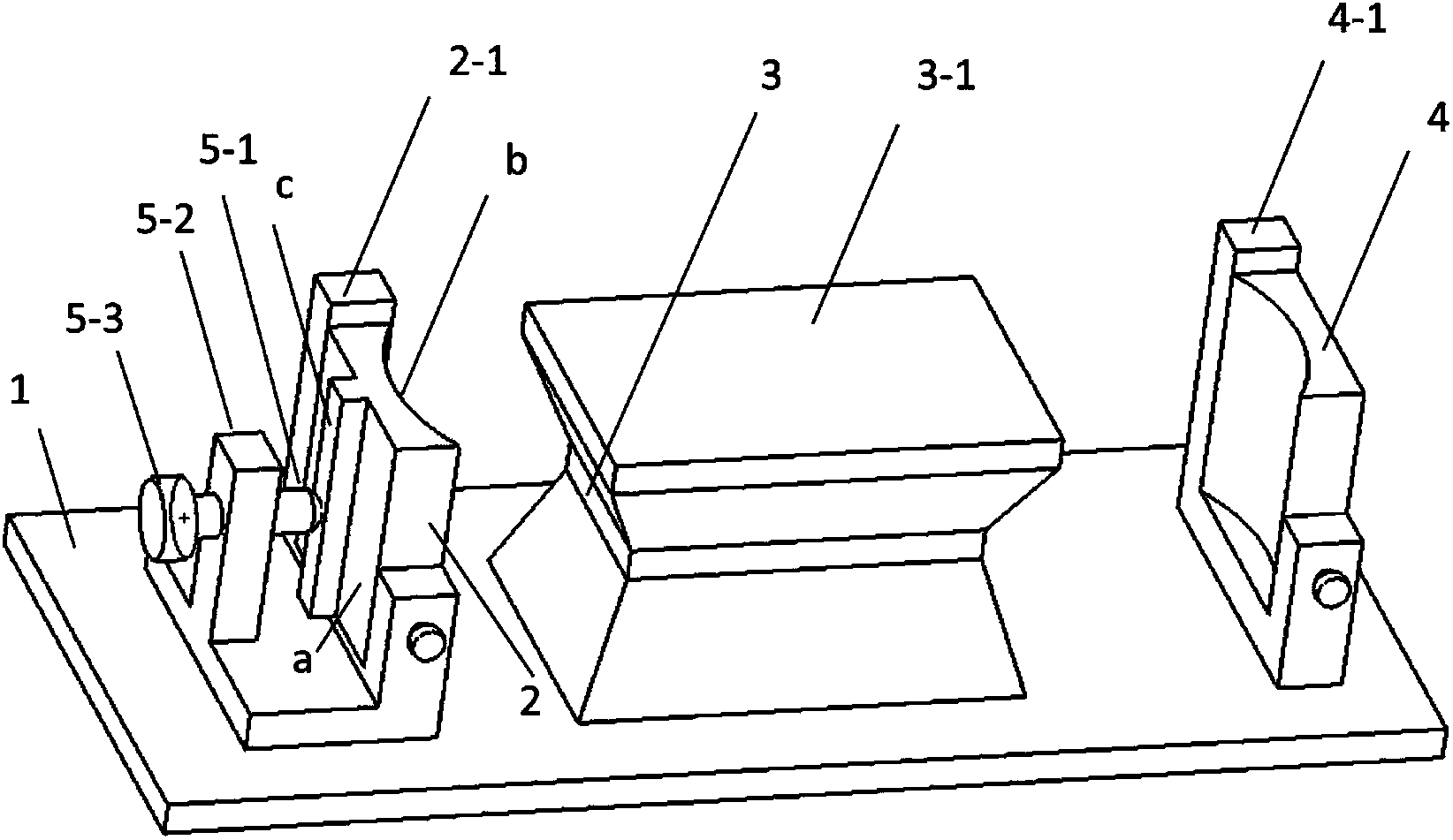
[0049] Such as Figure 4 , the ejector rod 5-1 is piezoelectric ceramic material, the ejector rod drive unit 5-3 is a piezoelectric ceramic power supply, the ejector rod 5-1 is connected to the ejector rod drive unit 5-3 through a cable, and the ejector rod support 5 in this embodiment The top of -2 has a card slot, and the ejector rod 5-1 is installed in the card slot, and the ejector rod 5-1 can move horizontally in the card slot. When there is no external voltage, the tip of the ejector rod 5-1 is in geometric contact with the pressure uniform distribution part c, and the voltage of the ejector rod drive unit 5-3 is adjusted to drive the ejector rod 5-1 to expand and contract, so that the ejector rod 5-1 acts on the column The force acting on the outer surface a of the mirror 2 changes, thereby achieving the purpose of changing the radius of curvature R of the inner surface b of the cylindrical mirror 2 .
[0050] Since the piezoelectric ceramic material can realize high-p...
PUM
 Abstract
Description
Claims
Application Information
 - R&D Engineer
- R&D Manager
- IP Professional
- Industry Leading Data Capabilities
- Powerful AI technology
- Patent DNA Extraction
Browse by: Latest US Patents, China's latest patents, Technical Efficacy Thesaurus, Application Domain, Technology Topic, Popular Technical Reports.
© 2024 PatSnap. All rights reserved.Legal|Privacy policy|Modern Slavery Act Transparency Statement|Sitemap|About US| Contact US: help@patsnap.com