Holding structure of intervening member, intervening member, and wobbling-prevention member

One component, one technology, applied in the direction of connecting components, mechanical equipment, transmission parts, etc., can solve the problems of reduced workability of rubber gaskets, high compressive loads, difficult clamping components, etc., to prevent the reduction of assembly workability, Reduced compressive load and easy adjustment

Active Publication Date: 2012-09-19
NIFCO INC
View PDF4 Cites 4 Cited by
  • Summary
  • Abstract
  • Description
  • Claims
  • Application Information

AI Technical Summary

Problems solved by technology

[0006] However, in the holding structure of the above-mentioned intervening member, in general, a rubber packing is used as the rattling prevention member, and the rubber packing is only temporarily fitted (temporarily fixed) in the recess formed in the intervening member, and the During the assembly work in which the intervening member is interposed between the first member and the second member, the rubber packing may come off from the recess of the intervening member
Therefore, when the rubber packing falls off, it is necessary to pick up the rubber packing and reassemble it again, and the fall of the rubber packing reduces workability.
[0007] In addition, when assembling the first member, the second member, and the intervening member, in order to restrict the rattling of the intervening member between the first member and the second member, the rubber packing as the rattling prevention member is compressed until it reaches a predetermined compressed state. , but in order to bring the rubber gasket into the specified compressed state, a very high compressive load is required
Therefore, when a rubber packing is used as the shaking prevention member, a member with high rigidity is required as an intervening member, and it is difficult to use an intervening member with low rigidity.

Method used


Image

  • Holding structure of intervening member, intervening member, and wobbling-prevention member
  • Holding structure of intervening member, intervening member, and wobbling-prevention member
  • Holding structure of intervening member, intervening member, and wobbling-prevention member

Examples


Embodiment Construction

[0053] Hereinafter, embodiments of the present invention will be described based on the drawings.

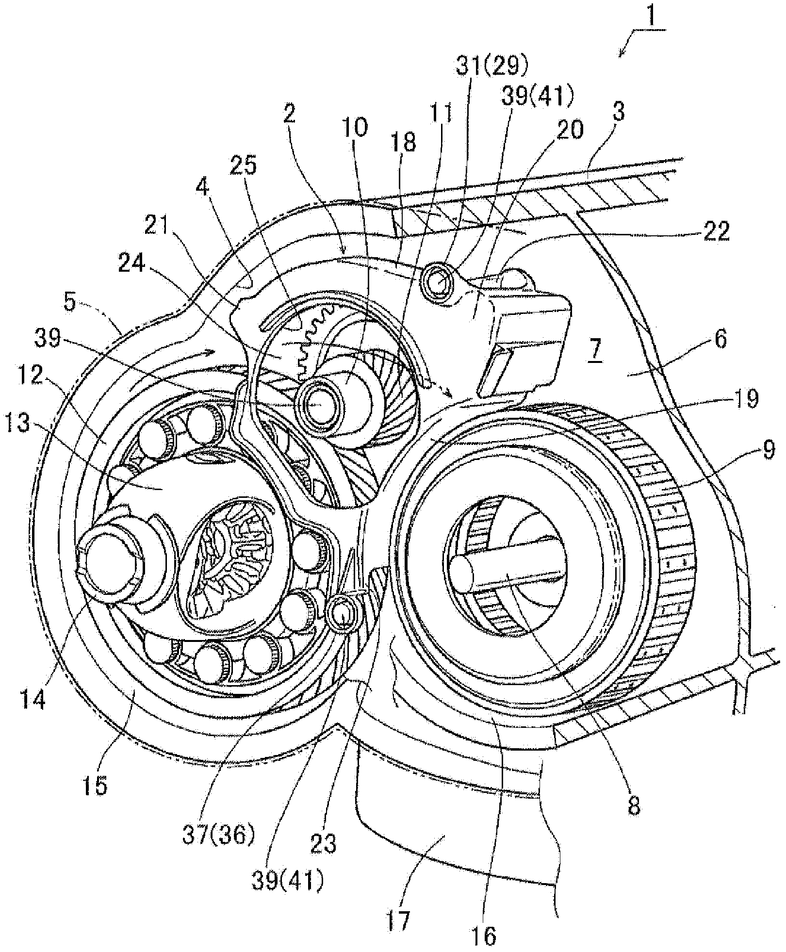
[0054] figure 1 The automatic transmission 1 incorporating the baffle 2 of the embodiment is shown. The automatic transmission 1 has a cylindrical transmission case (second member) 3, and an opening 4 on one side thereof is defined by a torque converter housing wall (first member, one side member: in figure 1 Indicated by a phantom line) 5 is blocked, and the opening (not shown) on the other side is blocked by an end cap (not shown). In the transmission case 3, an intermediate wall 6 is provided as a partition wall, and an input shaft for inputting power from the torque converter is arranged in a space 7 between the intermediate wall 6 and the torque converter housing wall 5. 8. The clutch drum 9 that transmits the power input to the input shaft 8 to the transmission mechanism (not shown) disposed between the intermediate wall 6 and the end cover, and the output gear 11 that r...


PUM


Abstract

A holding structure of an intervening member is provided for preventing the dropping-out of a wobbling-prevention member at an assembly time, and to extend an applicable range of rigidity of the intervening member to a low-side range. A baffle plate (2) is intervened between a torque converter housing wall (5) and an transmission case (3) (intermediate wall (6)), and a wobbling-prevention member (39) is a holding structure of the intervening member interposed between the baffle plate and the torque converter housing wall in a compressed state. Under the precondition, a bottom portion (31a (37a)) of a concave portion (31 (37)) is clamped between a head portion (41) and a bulging portion (42) of the wobbling-prevention member, so that the wobbling-prevention member is held in the bottom portion of the concave portion reliably even during the operation. Also, an inside of the head portion of the wobbling-prevention member is hollow, so when the head portion is crushed and deformed, the air inside the head portion is discharged to the outside through an annular gap (43) to reduce a compressive load relative to the baffle plate.

Description

technical field [0001] The present invention relates to a holding structure of an intervening member, an interposing member for the holding structure of the intervening member, and a sway preventing member for preventing wobbling of the intervening member. Background technique [0002] As the holding structure of the intervening member, there is a holding structure in which the intervening member is interposed between the first member and the second member. For example, in Patent Document 1, it is proposed that one end of the intervening member is attached to the first member in consideration of assembly, and on the other hand, the other end of the intervening member is provided with a rubber cover. The protruding end portion is fitted with the fitting portion formed on the second member. [0003] In addition, in the holding structure of the intervening member, there is a holding structure in which the intervening member is only held between the first member and the second ...

Claims


Application Information

Patent Timeline
Patent Type & Authority Applications(China)
IPC IPC(8): F16H57/021F16H57/023F16H57/028
CPCF16B21/086F16H57/0457F16H57/0423Y10T74/2186
Inventor 奥田知秀宫本诚司筱原昌子
Owner NIFCO INC
Why Eureka
Try Eureka