
Two-stage movable tooth speed reducing transmission device

A transmission device and movable tooth deceleration technology, applied in the direction of gear transmission device, transmission device, belt/chain/gear, etc., can solve the problems of large volume and complex structure, and achieve the effect of small volume, simple overall structure and easy connection

Inactive Publication Date: 2012-09-19
CHONGQING UNIV
View PDF6 Cites 5 Cited by
  • Summary
  • Abstract
  • Description
  • Claims
  • Application Information

AI Technical Summary

Problems solved by technology

[0002] In the traditional cycloidal gear reduction transmission, in order to ensure the balance of the transmission, there are two cycloidal gears in the cycloidal transmission structure of each stage of reduction. To achieve two-stage reduction, four cycloidal gears are required. Therefore, the traditional two-stage The structure of the cycloid transmission device is more complicated and the volume is larger

Method used


Image

  • Two-stage movable tooth speed reducing transmission device
  • Two-stage movable tooth speed reducing transmission device

Examples


Embodiment Construction

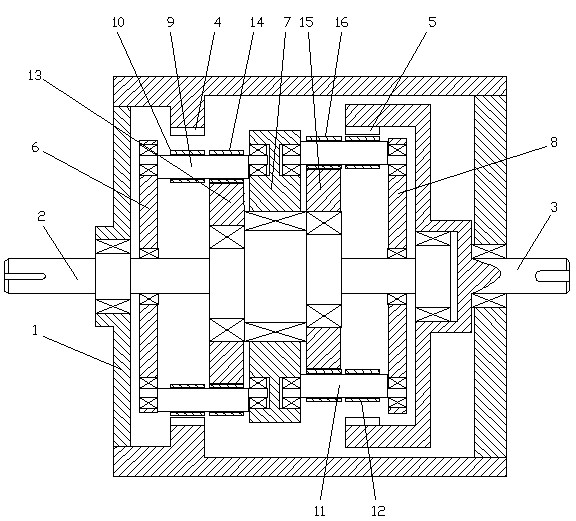
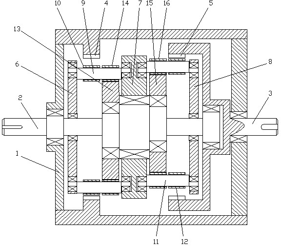
[0013] figure 1 It is a structural schematic diagram of the two-stage movable tooth reduction transmission device of the present invention.

[0014] As shown in the figure, the two-stage movable tooth reduction transmission device in this embodiment includes a housing 1, an eccentric input shaft 2, an output shaft 3, a first-stage internal gear 4, and a second-stage internal gear 5. The upper edge of the eccentric input shaft 2 In its axial direction, the first movable gear frame 6, the primary drive plate, the center plate 7, the secondary drive plate and the second movable gear frame 8 are arranged in sequence in rotation, wherein the primary drive plate and the secondary drive plate are located eccentrically. On the two eccentric shaft sections of the input shaft 2; the eccentric input shaft 2 and the output shaft 3 are arranged on the housing 1 and rotate with it, and the end of the eccentric input shaft 2 is arranged on the output shaft 3 and rotate with it ; The first-s...


PUM


Abstract

The invention discloses a two-stage movable tooth speed reducing transmission device which comprises a housing, an eccentric input shaft, an output shaft, first-stage internal gears and second-stage internal gears, wherein a first movable gear frame, a first-stage driving disc, a central disc, a second-stage driving disc and a second movable gear frame are arranged on the eccentric input shaft in sequence; the two-stage movable tooth speed reducing transmission device further comprises a first eccentric frame formed by first-stage cranks; first-stage movable gears are arranged on the first-stage cranks; a first-stage movable gear cluster is meshed with the first-stage internal gears with few tooth differences; the two-stage movable tooth speed reducing transmission device further comprises a second eccentric frame formed by second-stage cranks; and second-stage movable gears are arranged on the second-stage cranks and meshed with the second-stage internal gears with few tooth differences. According to the two-stage movable tooth speed reducing transmission device, only one pair of meshed internal and movable gears is arranged in each stage of speed reducing transmission device, so that the whole device has a simple structure and a small volume; a rotation center of the eccentric input shaft is coaxial with a rotation center of the output shaft, so that the transmission device can be conveniently connected with other transmission structures and the mounting space of the transmission device is reduced; and the two ends of the first-stage crank and the two ends of the second-stage crank are all supported, so that the cranks are stressed symmetrically and have great carrying ability.

Description

technical field [0001] The invention relates to a reduction transmission device, in particular to a cycloidal gear transmission device. Background technique [0002] In the traditional cycloidal gear reduction transmission, in order to ensure the balance of the transmission, there are two cycloidal gears in the cycloidal transmission structure of each stage of reduction. To achieve two-stage reduction, four cycloidal gears are required. Therefore, the traditional two-stage The cycloid transmission device has a complex structure and a large volume. [0003] Therefore, it is necessary to improve the cycloid transmission device in the prior art to simplify its structure and reduce its volume. Contents of the invention [0004] In view of this, the object of the present invention is to provide a two-stage movable tooth reduction transmission device, in which there is only one cycloidal gear in each reduction transmission structure, the overall structure is simple, and the vol...

Claims


Application Information

Patent Timeline
Patent Type & Authority Applications(China)
IPC IPC(8): F16H1/32
Inventor 朱才朝孙章栋季洋江张斌
Owner CHONGQING UNIV
Learn More