
Hydraulic drive continuously variable gas inlet system

An air intake system and variable technology, applied in the directions of fuel air intake, engine control, combustion engine, etc., can solve the problems of increasing air intake, large size and weight of the air intake system, and occupying a lot of space, so as to improve the performance of the air intake system. The effect of output power, improving intake efficiency, and improving economy

Inactive Publication Date: 2012-09-19
HARBIN ENG UNIV
View PDF12 Cites 6 Cited by
  • Summary
  • Abstract
  • Description
  • Claims
  • Application Information

AI Technical Summary

Problems solved by technology

The patent US6508331B1 changes the gas channel by adjusting the position of the retaining wall, but it is mainly used for noise reduction; the patent US2008066999A1 changes the structure of the intake system by adjusting the opening of the valve, but its main purpose is also to eliminate noise and increase the intake air volume. Little impact; the patent US0168961A1 achieves the purpose of increasing the intake air by changing the structure of the intake system using the intake through hole, but it is not continuously adjustable
The currently applied resonant intake system with variable intake manifold length changes the length of the intake manifold by changing the flow path of the intake air. Since the intake manifold includes two or three intake manifolds with different paths, The air intake system is large in size and weight, takes up a lot of space, and can only realize two-stage or three-stage variable manifold length, and the length of the intake manifold cannot be continuously changed, so the optimal resonance can only be achieved at several operating points air intake

Method used


Image

  • Hydraulic drive continuously variable gas inlet system
  • Hydraulic drive continuously variable gas inlet system
  • Hydraulic drive continuously variable gas inlet system

Examples


Embodiment Construction

[0021] The present invention is described in more detail below in conjunction with accompanying drawing example:

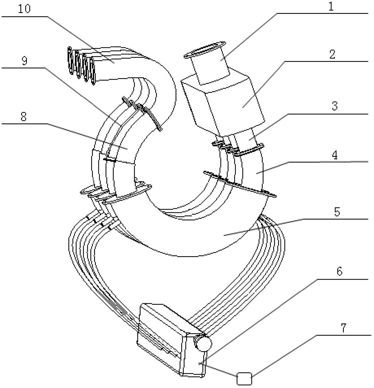
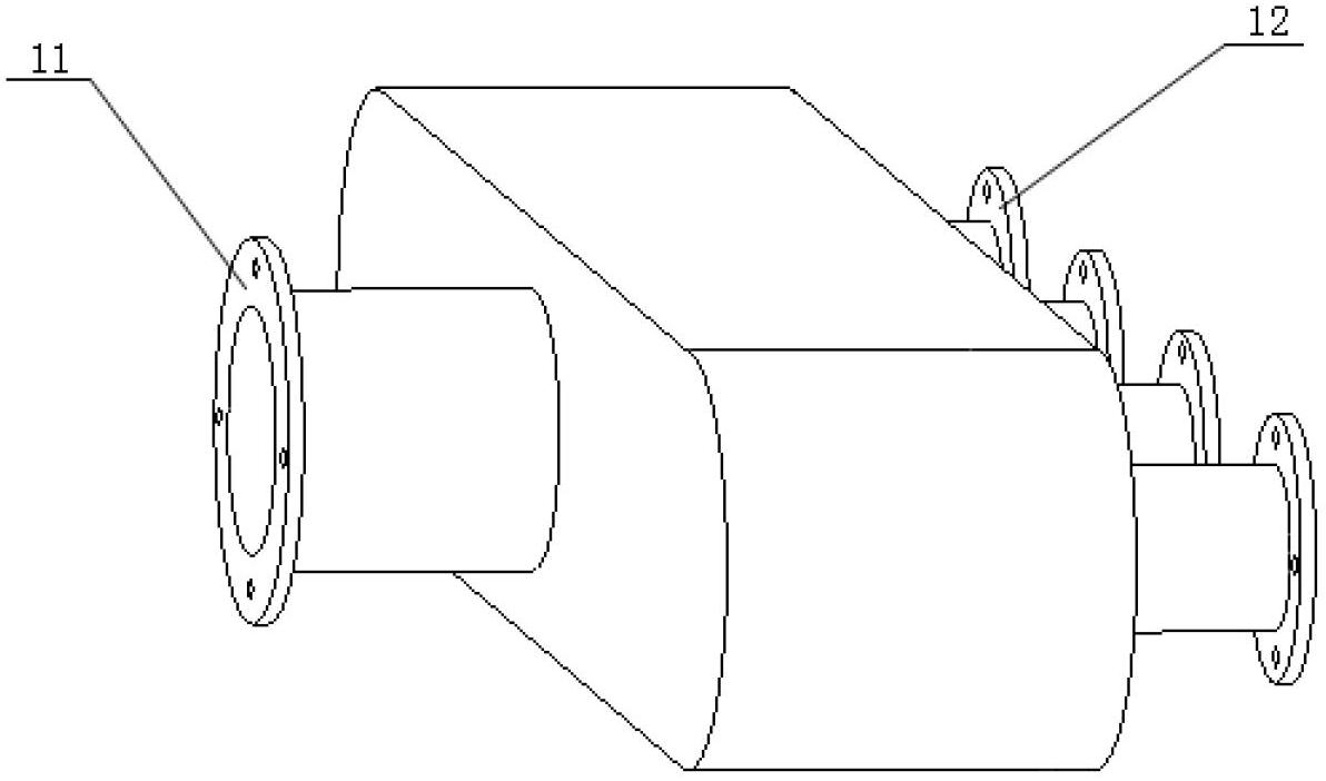
[0022] combine Figure 1-8 , the present invention includes an intake manifold 1, a resonant cavity 2, an intake manifold front section 3, an intake manifold middle outer tube 4, a hydraulic cavity 5, a hydraulic drive unit 6, a hydraulic control unit 7, and an intake manifold middle inner tube 8. The displacement measuring device 9 and the rear section 10 of the intake manifold. It is characterized in that: the front section 3 of the intake manifold, the outer tube 4 in the middle section of the intake manifold, the inner tube 8 in the middle section of the intake manifold and the rear section 10 of the intake manifold together constitute the intake manifold, and the outer tube in the middle section of the intake manifold 4 and the inner tube 8 in the middle section of the intake manifold can move relatively continuously, and the length of the intake manifold ch...


PUM


Abstract

The invention aims at providing a hydraulic drive continuously variable gas inlet system which comprises a gas inlet main pipe, a resonant cavity, gas inlet manifolds and hydraulic cavities, wherein the gas inlet main pipe, the resonant cavity and the gas inlet manifolds are sequentially connected, the length of the gas inlet manifolds can be changed, and the hydraulic cavities are sleeved on the gas inlet manifolds for adjusting the length of the gas inlet manifolds. According to the hydraulic drive continuously variable gas inlet system, under different working conditions, the length of the resonance gas inlet manifolds can be changed so that good resonance effects can be achieved in a wide rotation speed range of an engine, the gas inlet efficiency of the gas engine can be improved, the output power can be improved, and the economy is improved.

Description

technical field [0001] The invention relates to an engine, in particular to an intake system of the engine. Background technique [0002] With the development of the economy, the shortage of oil and environmental pollution are becoming more and more prominent. The development and use of new energy is an inevitable choice for human beings. The advantages of natural gas resources, such as rich resources, low emission pollution, and cheap prices, are increasingly valued by people. Therefore, natural gas engines have Wide market application prospects. [0003] At present, gas engines are mainly converted from diesel engines or gasoline engines. Due to the formation of a mixed gas engine outside the cylinder, the gas fuel occupies a certain amount of intake air, so that the amount of air inhaled by the gas engine is higher than that of diesel engines and diesel engines under the same working conditions. There are fewer gasoline engines, so the power density of gas engines is usu...

Claims


Application Information

Patent Timeline
Patent Type & Authority Applications(China)
IPC IPC(8): F02M35/10F02D9/02
CPCY02T10/14Y02T10/12
Inventor 杨立平靖海国马修真李文辉黄帅王晓斌
Owner HARBIN ENG UNIV
Learn More