Water stop device and method when excavation equipment enters receiving well
A water-stop device and technology for receiving wells, which are used in mining equipment, earth-moving drilling, tunnels, etc., can solve problems such as failure, high production costs, and inability to guarantee complete water-stopping.
- Summary
- Abstract
- Description
- Claims
- Application Information
AI Technical Summary
Problems solved by technology
Method used
Image
Examples
Embodiment 1
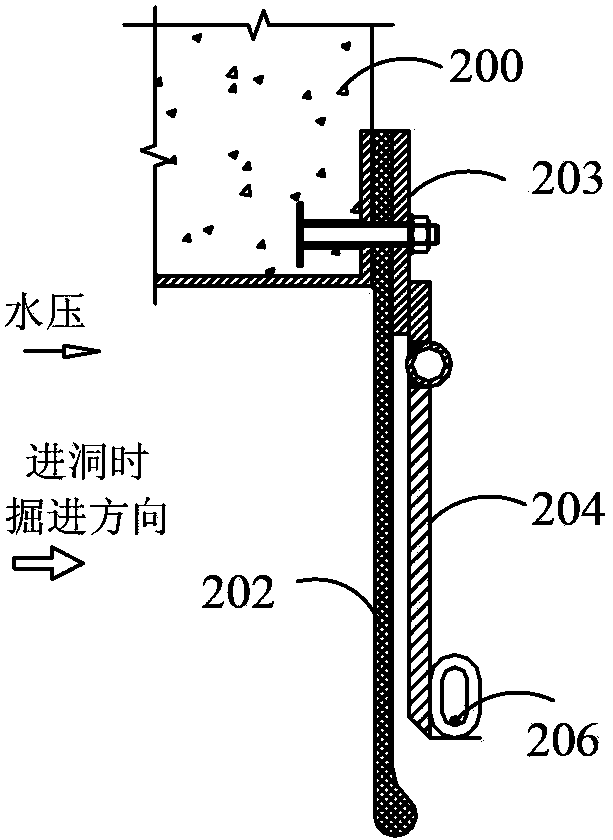
[0052] see image 3 , image 3 It is a structural schematic diagram of the water stop device when the excavation equipment enters the receiving well according to the first embodiment of the present invention. This embodiment provides a water stop device when the tunneling equipment enters the receiving well, which is used to stop the water when the tunneling equipment 300 enters the receiving well. Since the water is outside the receiving well, that is, outside the hole, the water pressure is mainly It is squeezed from the outside of the hole to the inside of the hole, where the water flows will generate water pressure at that position. The water stop device when the excavation equipment enters the receiving well: it includes an elastic cord 302 such as a rubber cord, a flap 304 and a pressing plate 303, and one end of the elastic cord 302 is fixedly installed on the periphery of the door opening of the enclosure structure 300 through the pressing plate 303, so The flap 304 ...
Embodiment 2
[0069] see Figure 10 The difference between this embodiment and Embodiment 1 is that the water-tight casing is installed around the door opening of the enclosure structure 300 through the support casing 400, and one end of the support casing 400 is fixed on the enclosure structure 300 Around the door opening, the other end of the support box 400 is installed with a door seal 500, the water-stop box is installed on the annular inner wall of the support box 400, and one end of the elastic cord 302 in the water-stop box is fixed by a pressure plate 303 on the annular inner wall of the support box 400 . The second connection holes 307 are respectively fixedly connected with the corresponding positions on the annular inner wall of the support box 400 and the corresponding movable plate, and the water stop device also includes a number of first bolt assemblies annularly distributed along the annular inner wall of the support box 400 310 , the first bolt assembly 310 fixedly instal...
Embodiment 3
[0074] see Figure 11 , the difference between this embodiment and the second embodiment is: the number of the support sleeves 400 is two or more, the number of the water-tight sleeves is the same as the number of the support sleeves 400, the support The casings 400 are connected sequentially, wherein, the end of the supporting casing 400 close to the enclosure structure 300 is fixedly connected to the periphery of the enclosure structure 300, and the end of the supporting casing 400 away from the enclosure structure 300 is far away from the enclosure. The end of the structure 300 is provided with the sealing door 500, and the water-tight casings are respectively arranged on the annular inner walls of the corresponding support casings 400, and one end of the elastic cord 302 in each water-tight casing is fixed to the corresponding pressure plate 303. The annular inner wall of the supporting sleeve 400. In this embodiment, leak-stopping materials may also be filled between mul...
PUM
 Abstract
Description
Claims
Application Information
 - R&D
- Intellectual Property
- Life Sciences
- Materials
- Tech Scout
- Unparalleled Data Quality
- Higher Quality Content
- 60% Fewer Hallucinations
Browse by: Latest US Patents, China's latest patents, Technical Efficacy Thesaurus, Application Domain, Technology Topic, Popular Technical Reports.
© 2025 PatSnap. All rights reserved.Legal|Privacy policy|Modern Slavery Act Transparency Statement|Sitemap|About US| Contact US: help@patsnap.com


