
Elevator traction machine of steel wire rope antiskid device

A technology of elevator traction machine and anti-skid device, which is applied to elevators, elevators, transportation and packaging in buildings, etc. It can solve the problems of increasing the friction force of the traction wheel on the wire rope, etc., and achieve the effect of simple and practical working mode

Inactive Publication Date: 2012-09-19
郭自刚
View PDF6 Cites 5 Cited by
  • Summary
  • Abstract
  • Description
  • Claims
  • Application Information

AI Technical Summary

Problems solved by technology

Make the brake pads run downwards, apply a braking force to the surface of the wire rope above the traction sheave, and instantly increase the friction between the traction sheave and the wire rope, the wire rope will stop sliding immediately, and at the same time trigger the control system to make the traction machine brake This device can not only solve the problem of wire rope over-travel sliding, but also has a strong positive pressure on the surface of the wire rope, which not only increases the friction force of the traction wheel on the wire rope, but also increases the traction of the brake on the wire rope. The relative motion friction between the wheels acts as an auxiliary braking effect
It can effectively solve the problem of the elevator sliding due to insufficient friction, resulting in the phenomenon of rushing to the top or squatting at the bottom. It also has an auxiliary braking function under specific conditions. When there is a problem with the braking function of the traction machine brake, the signal collection point will be activated. Over-speed sampling feedback, the device works to brake the surface of the traction sheave wire rope to achieve auxiliary braking and play a secondary protective effect

Method used


Image

  • Elevator traction machine of steel wire rope antiskid device
  • Elevator traction machine of steel wire rope antiskid device
  • Elevator traction machine of steel wire rope antiskid device

Examples


Embodiment Construction

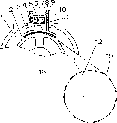
[0022] An elevator traction machine of a steel wire rope anti-skid device of the present invention, such as figure 1 figure 2 , including traction machine main body, brake pad (4), brake shoe (5), column (6), compression plate (7), adjustment nut (8), compression spring (9) or extension spring (16), The electromagnetic brake (10) can be direct suction or inclined block type and elevator related parts, steel wire rope and guide wheel or counterweight wheel.

[0023] Embodiment 1 of the present invention adopts direct-suction braking, sets a sampling point (18) on the guide wheel of the elevator, and sets up a sampling point (19) on the traction machine, when the elevator is running normally, suddenly When a power failure occurs, or the brake of the traction machine works due to a fault, the traction sheave stops or rotates slightly, while the car, wire rope, and guide wheel will continue to work due to inertia, causing the traction sheave and the wire rope to appear. Slippin...


PUM


Abstract

The invention relates to an elevator traction machine of a steel wire rope antiskid device. The elevator traction machine comprises a main body of the elevator traction machine, a traction sheave, a steel wire rope, a brake pad, a brake shoe, an upright column, a compressing plate, a regulating nut, an electromagnet and an electromagnetic coil. The elevator traction machine is characterized in that a danger emergency protective device is arranged on the traction machine; the danger emergency protective device comprises the brake pad, the brake shoe, the upright column, the compressing plate, a compression spring, the electromagnet and the electromagnetic coil; the brake pad can be made of a composite engineering material or metal material with high frictional factors; the electromagnetic coil can adopt a single-coil or multi-coil manner; the compressing plate can adjust the size of the frictional force through the upright column and the regulating nut when the device works; and the elevator traction machine can lead the working process of an elevator to be safer and reliable and has simple structure and good implementing effect.

Description

technical field [0001] The invention relates to an elevator traction machine, in particular to an elevator traction machine with a wire rope anti-skid device, and belongs to the field of elevator manufacturing. Background technique [0002] In the existing elevator installation and manufacture, there is still no effective solution to the sliding problem of the steel wire rope, because the elevator brakes instantaneously when the elevator is in a power failure during operation, and the car will generate a large impact force at this time. It will inevitably cause hidden dangers to personnel safety. Therefore, in order to prevent this phenomenon in the elevator design process, the steel wire rope is used for buffering. When the people on the level floor enter and leave, once there are too many people entering, the weighing alarm device will fail or some people will enter forcibly, which will cause the slide to be dangerous. At present, most elevator safety accidents in the worl...

Claims


Application Information

Patent Timeline
Patent Type & Authority Applications(China)
IPC IPC(8): B66B11/04B66B5/24
Inventor 郭自刚
Owner 郭自刚
Learn More