Dental orthodontic self-locking supporting groove

A self-locking bracket and bracket technology, applied in the field of orthodontics, can solve the problems of high price, difficult operation and high cost, and achieve the effects of convenient production, simple and convenient operation and good effect.

Active Publication Date: 2012-09-19
ZHEJIANG SHINYE MEDICAL TECH CORP LTD
View PDF9 Cites 8 Cited by
  • Summary
  • Abstract
  • Description
  • Claims
  • Application Information

AI Technical Summary

Problems solved by technology

At present, there are many kinds of self-locking brackets on the market, including two series of active type and passive type, but the...

Method used


Image

  • Dental orthodontic self-locking supporting groove
  • Dental orthodontic self-locking supporting groove
  • Dental orthodontic self-locking supporting groove

Examples


Embodiment

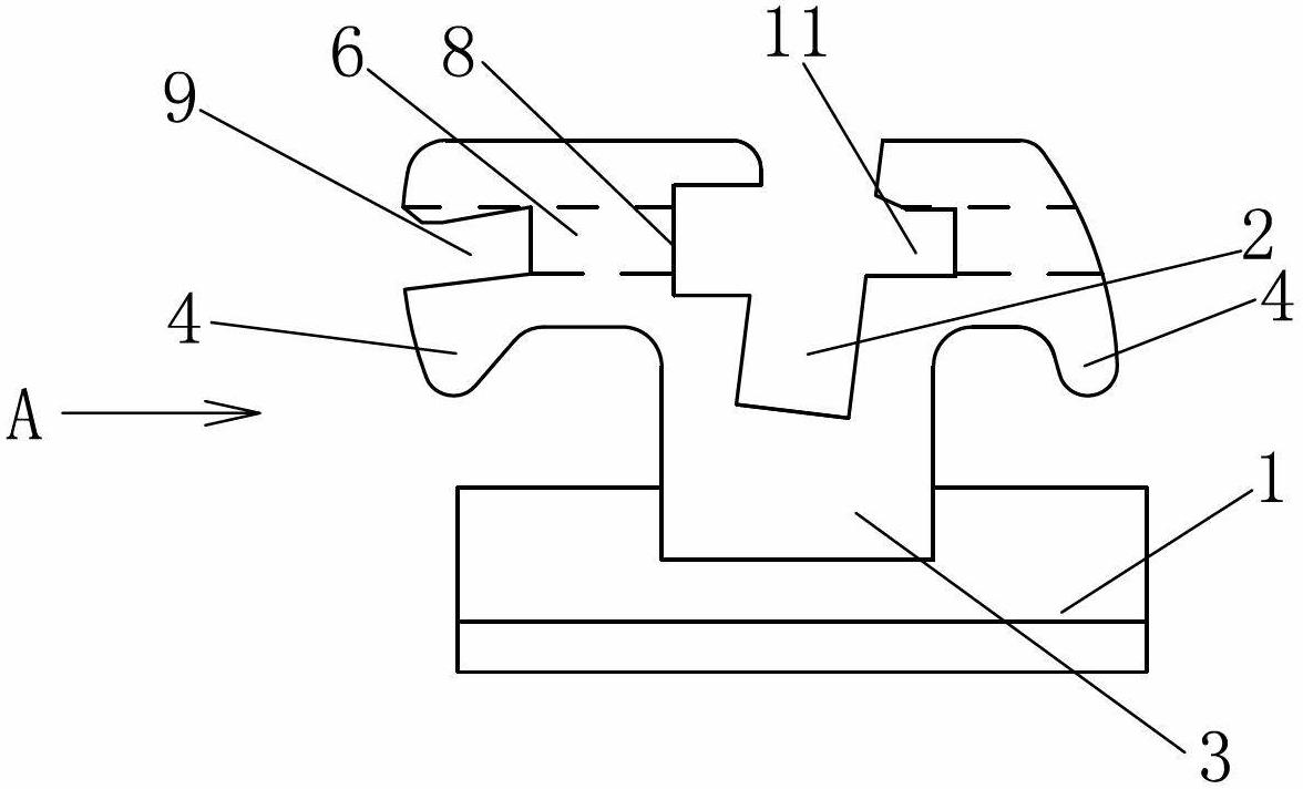
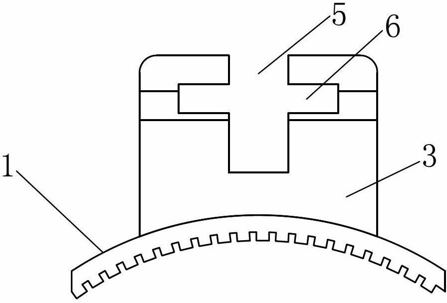
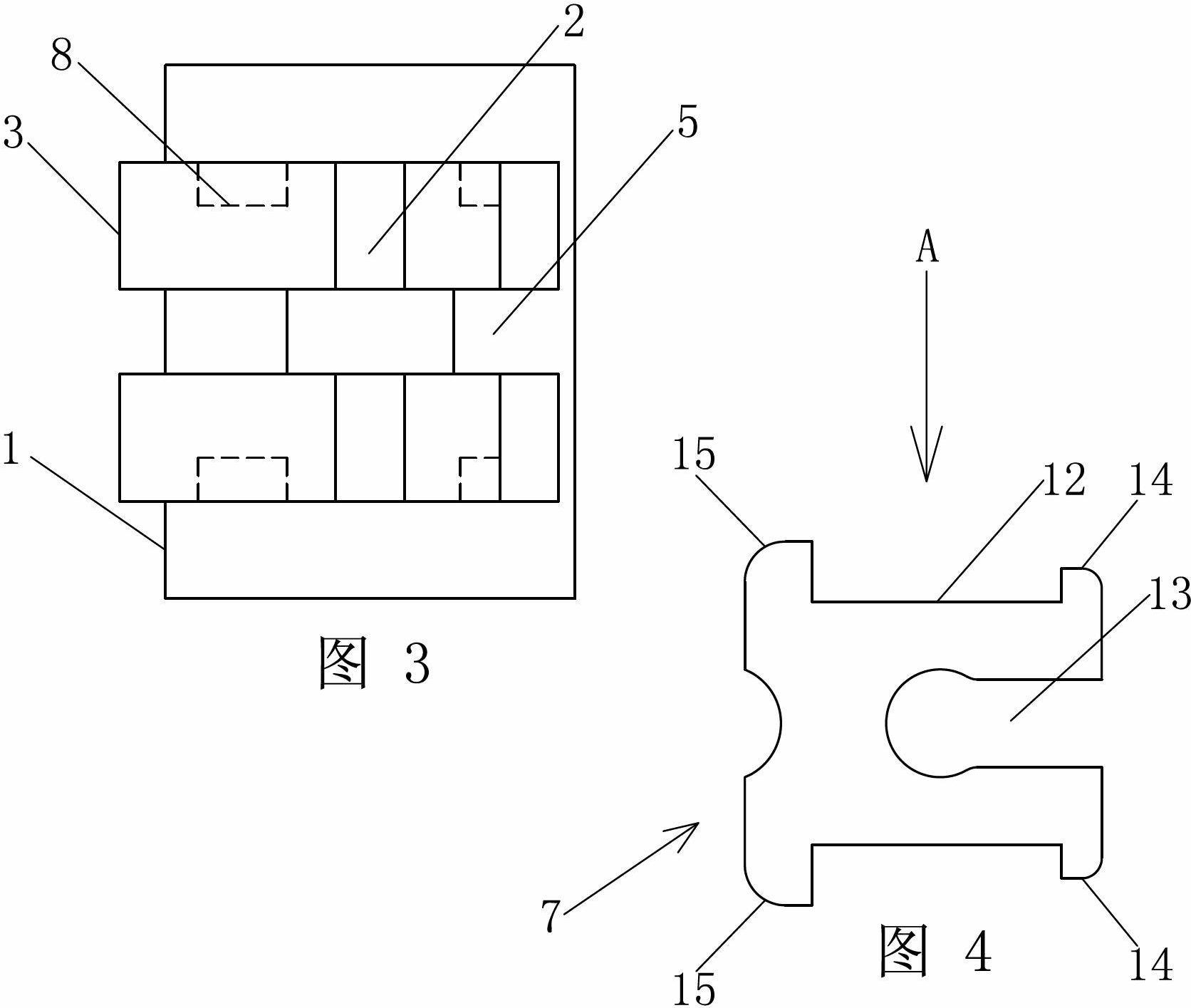
[0022] Embodiment: a kind of orthodontic self-ligating bracket for teeth, such as Figure 1~3 As shown, it includes a base plate 1 and a bracket body 3 with an archwire groove 2, the base plate 1 is arranged at the bottom of the bracket body 3, and is welded together with the bracket body 3; The working wing 4 is provided with a bracket opening 5 intersecting the arch wire groove 2 on the bracket body 3, and the bracket opening 5 is arranged to cross the arch wire groove 2. 4 divided into four separate pieces, such as figure 1 As shown by the dotted line in the middle, the two sides of the bracket opening 5 are symmetrically provided with a chute 6 cut by wire, and a groove edge 8 is vertically arranged in the chute 6, as Figure 6 , Figure 7 As shown, a bracket cover 7 is slid in the chute 6, and the bracket cover 7 is made of elastic material, which can produce elastic deformation.

[0023] Such as Figure 4 , Figure 5 As shown, the two sides of the bracket cover 7 ar...


PUM


Abstract

The invention discloses a dental orthodontic self-locking supporting groove, which comprises a base plate and a supporting groove body with an arc wire slot. The supporting groove body is provided with a supporting groove port at the intersection of the supporting groove body and the arc wire slot; slide grooves formed by wire-electrode cutting are symmetrically arranged at the two sides of the supporting groove port; groove sides are vertically arranged in the slide grooves; supporting groove covers made from elastic materials are arranged in the slide grooves in a sliding manner; slide bars are arranged at the two sides of each supporting groove cover; front wing hooks and rear wing hooks are respectively arranged at front ends and rear ends of outer sides of the slide bars; the two sides of the start ends of the slide grooves at the left sides of the groove sides are provided with chutes along the insertion direction of the supporting groove covers; the two sides of terminal ends of the slide grooves are provided with horn grooves; the openings of the horn grooves are reduced along the insertion direction of the supporting groove covers; and the height of upper end faces of at least one part of chutes and the horn grooves is lower than the upper end faces of the slide grooves. As long as the supporting groove covers are pushed to the end, the wing hooks at the front ends and the rear ends of the supporting groove covers bend, the supporting groove covers are subjected to elastic deformation by using the three kinds of grooves which are not located in the same plane, and thus, the aim of self locking is reached. The tedious operation of steel wire ligature is saved.

Description

technical field [0001] The invention relates to the technical field of orthodontics, in particular to an orthodontic self-locking bracket for teeth. Background technique [0002] At present, in the process of orthodontic treatment of oral teeth, the orthodontic bracket is fixed on the tooth surface, and the arch wire passes through the archwire slot (also known as the square wire slot) on the bracket, and is bound by a rubber ring or a steel wire. The arch wire is directly tied to the bracket ligation wing, and the correction force of the arch wire is transmitted to the teeth through the bracket, so that the teeth can move as expected, so as to achieve the purpose of correcting the teeth. [0003] Since the currently used ligation rubber ring or ligation steel wire is ligated on the ligation wing of the bracket, it directly exerts force on the arch wire, which produces a large pressure on the arch wire, hinders the normal movement of the arch wire, and thus affects the teeth...

Claims


Application Information

Patent Timeline
IPC IPC(8): A61C7/14
Inventor 王光良
Owner ZHEJIANG SHINYE MEDICAL TECH CORP LTD
Why Eureka
Try Eureka