Liquid crystal display device
A liquid crystal display device and signal line technology, which is applied in the directions of instruments, nonlinear optics, optics, etc., can solve the problems of reduced brightness, reduced display quality, and inability to display the color of objects, and achieves the effect of suppressing the offset.
- Summary
- Abstract
- Description
- Claims
- Application Information
AI Technical Summary
Problems solved by technology
Method used
Image
Examples
Embodiment approach 1
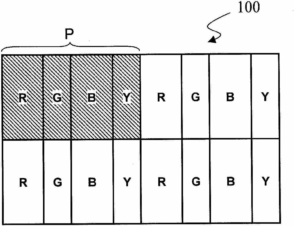
[0061] figure 1 The liquid crystal display device 100 in this embodiment is shown. Such as figure 1 As shown, the liquid crystal display device 100 has a plurality of pixels arranged in a matrix including a plurality of rows and a plurality of columns. The plurality of pixels include a red pixel R that displays red, a green pixel G that displays green, a blue pixel B that displays blue, and a yellow pixel Y that displays yellow. One picture element P, which is the minimum unit for performing color display, is defined by four consecutive pixels in the row direction. In each picture element P, four pixels are arranged in the order of red pixel R, green pixel G, blue pixel B, and yellow pixel Y from left to right.
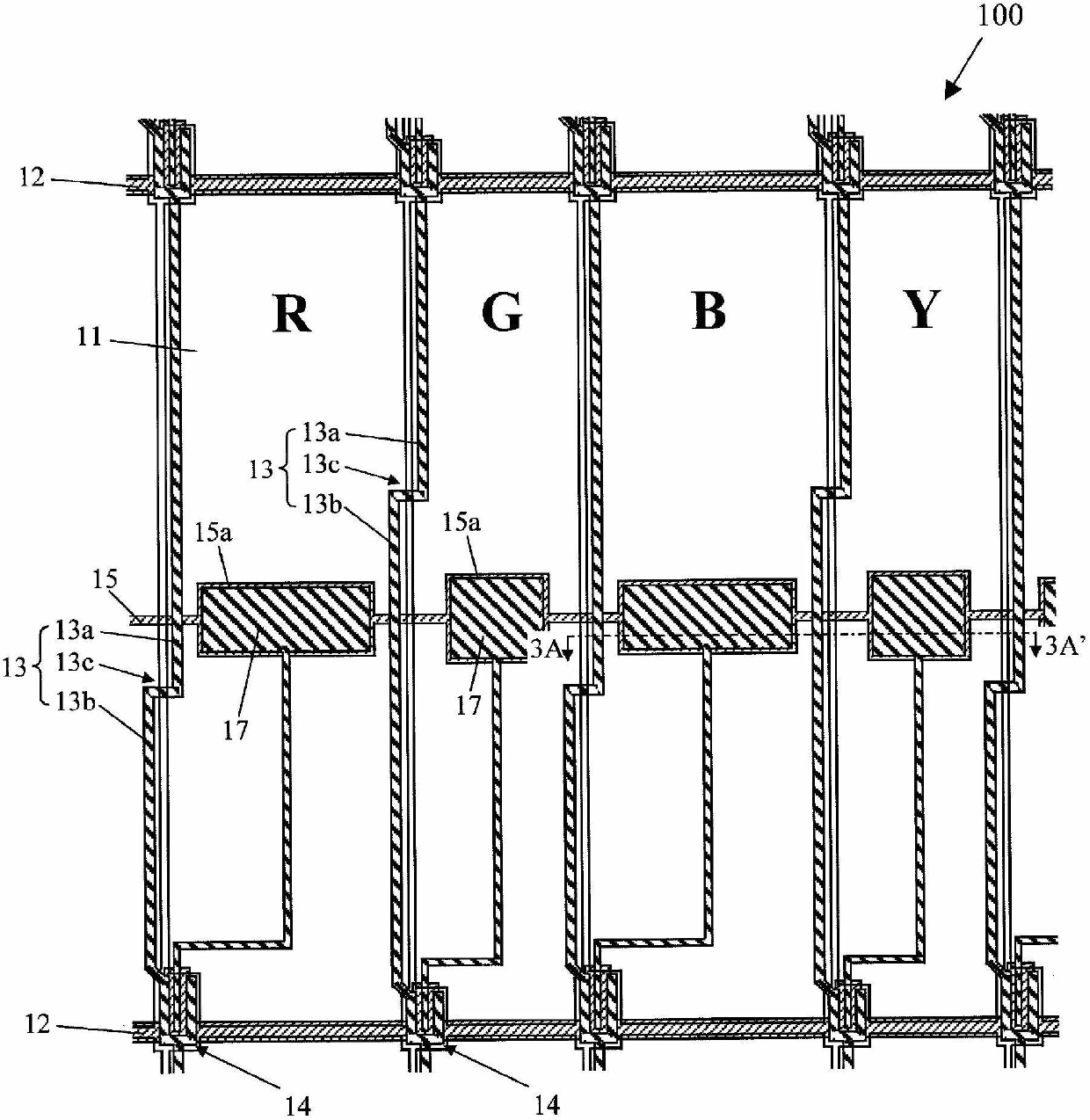
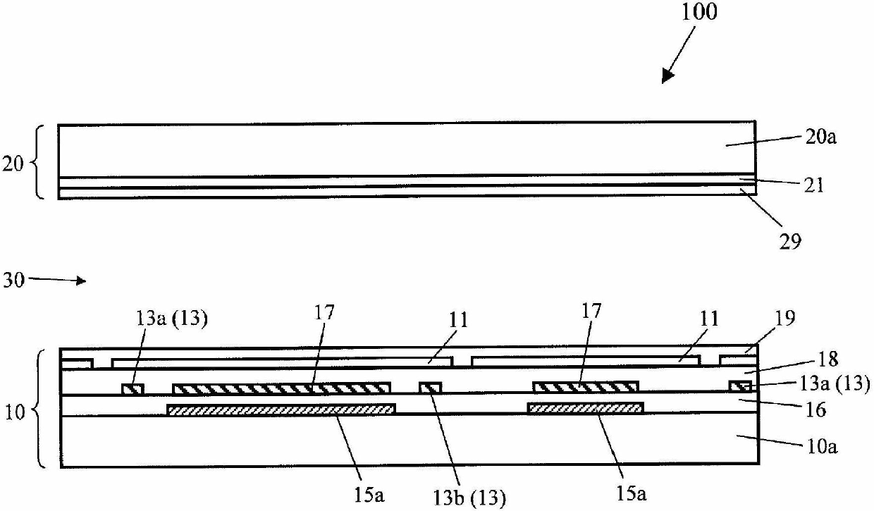
[0062] Such as figure 1 As shown, in the liquid crystal display device 100 , the area of the red pixel R and the blue pixel B is larger than the area of the green pixel G and the yellow pixel Y. That is, in the present embodiment, each pixel row of a plura...
Embodiment approach 2
[0086] refer to Figure 5 with Image 6 , the liquid crystal display device 200 in this embodiment will be described. In the liquid crystal display device 200, such as Figure 5 with Image 6 As shown, the areas of the red pixel R, the green pixel G and the blue pixel B are relatively large, and the area of the yellow pixel Y is relatively small. That is, the red pixel R, the green pixel G, and the blue pixel B are large pixels, and the yellow pixel Y is a small pixel.
[0087] In each picture element P, 4 pixels are sequentially arranged with red pixel R, green pixel G, blue pixel B, and yellow pixel Y from left to right. Therefore, along the row direction, large pixels, large pixels, large pixels, and small pixels are repeatedly arranged in the order.
[0088] In the liquid crystal display device 200 , the positions of the bent portions 13 c in the column direction of any two adjacent signal lines 13 in the row direction among the plurality of signal lines 13 are diff...
Embodiment approach 3
[0092] refer to Figure 7 with Figure 8 , the liquid crystal display device 300 in this embodiment will be described. In the liquid crystal display device 300, such as Figure 7 with Figure 8 As shown, each picture element P is defined by a red pixel R, a green pixel G and a blue pixel B. Therefore, the liquid crystal display device 300 is not a multi-primary-color liquid crystal display device, but a three-primary-color liquid crystal display device. Also, the areas of the red pixel R, the green pixel G, and the blue pixel B are equal to each other. That is, in the liquid crystal display device 300 , the area of the pixels is uniform, and there is no mixture of large pixels and small pixels.
[0093] In the liquid crystal display device 300 , the positions of the bent portions 13 c in the column direction of any two adjacent signal lines 13 in the row direction among the plurality of signal lines 13 are different from each other. Therefore, the area of the region ...
PUM
 Abstract
Description
Claims
Application Information
 - Generate Ideas
- Intellectual Property
- Life Sciences
- Materials
- Tech Scout
- Unparalleled Data Quality
- Higher Quality Content
- 60% Fewer Hallucinations
Browse by: Latest US Patents, China's latest patents, Technical Efficacy Thesaurus, Application Domain, Technology Topic, Popular Technical Reports.
© 2025 PatSnap. All rights reserved.Legal|Privacy policy|Modern Slavery Act Transparency Statement|Sitemap|About US| Contact US: help@patsnap.com


