Electrical discharge machining device
An electrical discharge machining and machining fluid technology, applied in electric machining equipment, metal machining equipment, circuits, etc., to solve problems such as electrode damage, abnormal consumption, and slow machining speed.
- Summary
- Abstract
- Description
- Claims
- Application Information
AI Technical Summary
Problems solved by technology
Method used
Image
Examples
Embodiment 1
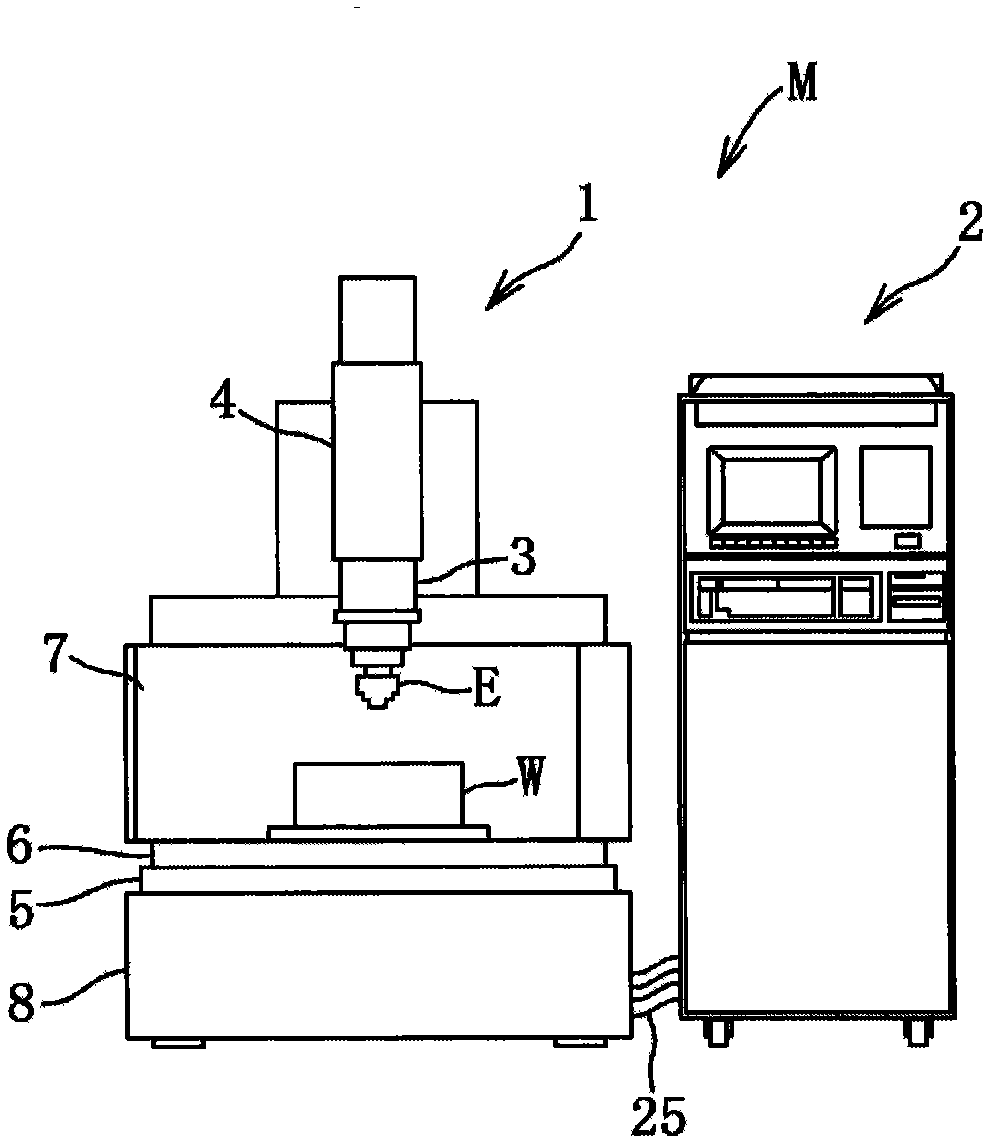
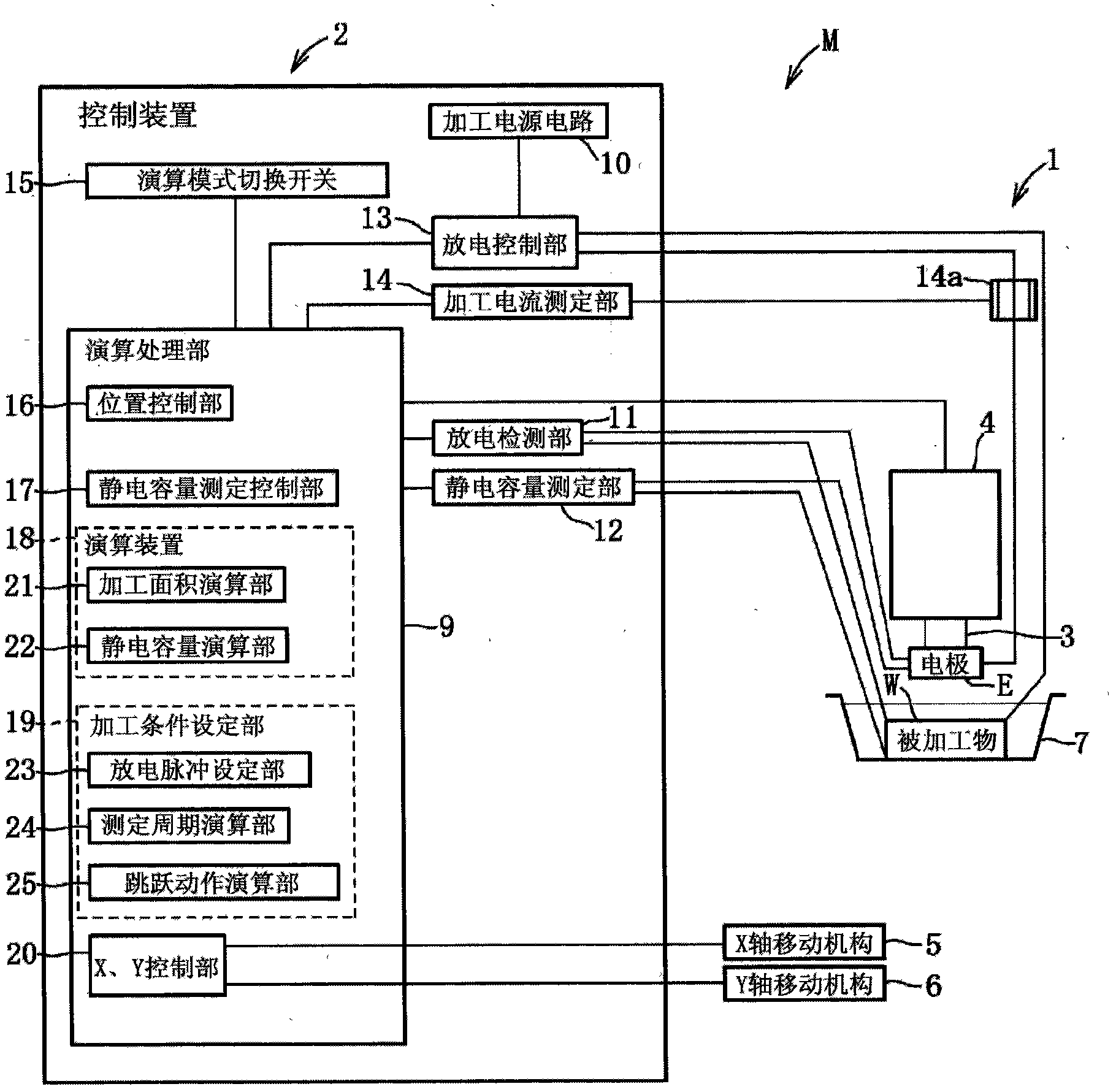
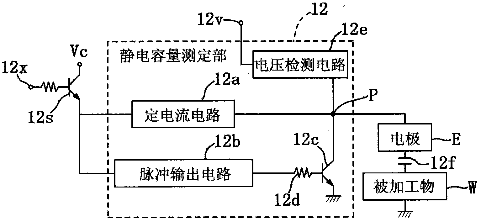
[0096] Below, based on Figure 1 to Figure 10 Examples of the present invention will be described.
[0097] like figure 1 As shown, the electrical discharge machining device M is a device that supplies a machining fluid to the gap between the electrode E and the workpiece W, and applies a discharge pulse from the electrode E to the workpiece W to perform electrical discharge machining on the workpiece W. . This electrical discharge machining device M has peripheral equipment such as a machining machine body 1 , a control device 2 , and a machining liquid tank 7 . The processing machine body 1 is composed of: a head 3 equipped with an electrode E; a Z-axis moving mechanism 4 (moving device) as a feeding device that can reciprocate the head 3 in the up and down direction (Z-axis); an X-axis moving mechanism 5. The machining liquid tank 7 containing the workpiece W can be placed along the figure 1 The horizontal reciprocating movement in the left and right direction (X axis);...
Embodiment 2
[0175] Second, based on Figure 11 Example 2 will be described.
[0176] The difference from Example 1 is that the distance D from the surface of the workpiece W in Example 1 to the processing surface is known, but the distance D in Example 2 is unknown.
[0177] The columnar electrode EB is brought into contact with the processing surface of the workpiece W to initialize the moving position (interpolar distance) of the electrode EB. Secondly, if Figure 11 As shown in (a), the electrode EB is moved upwards by the Z-axis moving mechanism 4 to move the electrode EB to the first moving position. At this time, if it is set as: the first total electrostatic capacity C31, the inter-electrode electrostatic capacity Cp31 between the electrode advancing end surface and the processing surface, the processing area SB, the first two-pole distance h31 from the electrode advancing end surface to the processing surface, and the side surface of the electrode EB The electrostatic capacitan...
Embodiment 3
[0195] Second, based on Figure 12 Example 3 will be described.
[0196] It differs from Example 1 in that: the distance D from the surface of the workpiece W in Example 1 to the processing surface is known, while the distance D in Example 3 is unknown and the measured distance between two poles includes an error distance alpha. In addition, the error distance α is caused by machining chips accumulated on the machining surface of the workpiece W or the backlash of the gear system of the Z-axis moving mechanism 4. When no backlash occurs, the machining debris on the machining surface The accumulation amount of is represented by a positive value, and when a backlash occurs, it represents the total value of the negative value of the backlash amount and the positive value of the accumulation amount of machining debris.
[0197] The columnar electrode EC is brought into contact with the processing surface of the workpiece W to initialize the moving position (distance between elec...
PUM
 Abstract
Description
Claims
Application Information
 - R&D
- Intellectual Property
- Life Sciences
- Materials
- Tech Scout
- Unparalleled Data Quality
- Higher Quality Content
- 60% Fewer Hallucinations
Browse by: Latest US Patents, China's latest patents, Technical Efficacy Thesaurus, Application Domain, Technology Topic, Popular Technical Reports.
© 2025 PatSnap. All rights reserved.Legal|Privacy policy|Modern Slavery Act Transparency Statement|Sitemap|About US| Contact US: help@patsnap.com


