
Active and reactive coordination control method for permanent-magnet direct-driven wind turbines in low-voltage ride-through process

A low-voltage ride-through, wind turbine technology, applied in reactive power adjustment/elimination/compensation, reactive power compensation, single-grid parallel feeding arrangement, etc. It can improve the low voltage ride-through capability, reduce the DC voltage fluctuation, and reduce the active power loss.

Inactive Publication Date: 2012-09-12
NORTH CHINA ELECTRIC POWER UNIV (BAODING)
View PDF2 Cites 69 Cited by
  • Summary
  • Abstract
  • Description
  • Claims
  • Application Information

AI Technical Summary

Problems solved by technology

These methods all need to increase the external hardware circuit, which not only increases the volume and cost of the converter, makes the controller more complicated, but also causes the active power loss of the wind turbine.
At the same time, when the grid voltage drops, the wind turbines cannot provide timely dynamic reactive power support to the grid due to the current limitation of the grid-side converter, which makes little contribution to the recovery of the grid-connected point voltage.

Method used


Image

  • Active and reactive coordination control method for permanent-magnet direct-driven wind turbines in low-voltage ride-through process
  • Active and reactive coordination control method for permanent-magnet direct-driven wind turbines in low-voltage ride-through process
  • Active and reactive coordination control method for permanent-magnet direct-driven wind turbines in low-voltage ride-through process

Examples


Embodiment Construction

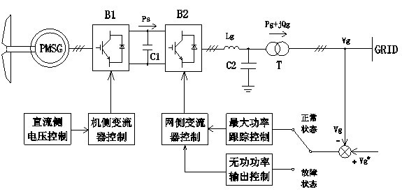
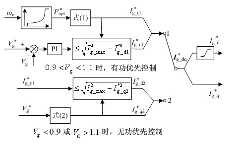
[0032] According to the change degree of the grid voltage amplitude, the invention realizes the coordinated control of the active power and reactive power of the wind turbine before and after the grid voltage mutation by switching the control strategy of the grid side converter. see figure 1 , when the grid voltage is in the normal range, the maximum power tracking control is realized through the grid-side converter, and the machine-side converter controls the DC voltage to be stable. When the grid voltage fails, the grid-side converter is controlled to implement reactive power priority control mode, and the inertial energy storage of the wind turbine is used to share the sudden change of active power at both ends of the DC bus capacitor, reducing the active power loss of the wind turbine unit and stabilizing the DC bus voltage. Enhance the fault ride-through capability of the wind power system, and quickly and accurately provide reactive power support to the grid to support ...


PUM


Abstract

Enclosed is an active and reactive coordination control method for permanent-magnet direct-driven wind turbines in the low-voltage ride-through process. Two different control strategies are employed for a grid side converter according to amplitude change of power grid voltage: when the power grid voltage is in a normal state, the grid side converter is in an active-priority maximum power tracing control mode so that the wind turbines capture wind energy to the maximum extent; when the power grid voltage is beyond the normal range, the grid side converter is in an active priority control mode so that the dynamic reactive current which is injected into an electricity system meets the requirements of grid combining. An engine side converter is in a direct-current voltage control mode based on rotor energy storage, power unbalance of the direct-current side of the engine side converter is relieved and the direct-current voltage is stabilized by utilizing the self rotating speed of the permanent-magnet direct-driven wind turbines and the change of the kinetic energy. The active and reactive coordination control for the wind turbines before or after the sudden change of the power grid voltage is realized according to the amplitude change of the power grid voltage, the fluctuation of the direct-current bus voltage is restrained by releasing or storing the rotor kinetic energy, so that the low-voltage ride-through capability of the permanent-magnet direct-driven wind turbines is improved, reactive power support is rapidly and accurately provided for the power grid, and certain support is given to restoration of the power grid voltage.

Description

technical field [0001] The invention relates to a power control method of a permanent magnet direct drive wind power generating set, which can improve the stability of the wind generating set during low-voltage ride-through, and provide dynamic reactive power support for a power grid, belonging to the technical field of power generation. Background technique [0002] In recent years, the low-voltage ride-through problem of grid-connected direct-drive permanent magnet wind turbines has attracted great attention from wind turbine manufacturers. The key technical problem in realizing low voltage ride-through of the permanent magnet direct drive synchronous generator set connected to the grid through the full power converter is to maintain the stability of the DC link capacitor voltage of the converter. The traditional technical solution is mainly to install an unloading circuit on the DC side, an energy storage device to absorb excess energy, or connect an auxiliary converter i...

Claims


Application Information

Patent Timeline
IPC IPC(8): H02J3/38H02J3/18
CPCY02E40/30
Inventor 王毅董淑恵任亚钊李和明
Owner NORTH CHINA ELECTRIC POWER UNIV (BAODING)
Learn More