Sintered and sealed electric connector resistant to high pressure

A technology of sintering sealing and electrical connectors, which is applied in the direction of connection and connection device components, circuits, etc., can solve the problems of poor compression resistance of electrical connectors, and achieve the effects of quality assurance, easy quality, and sintering quality solutions

Inactive Publication Date: 2012-09-12
CHINA AVIATION OPTICAL-ELECTRICAL TECH CO LTD
View PDF8 Cites 4 Cited by
  • Summary
  • Abstract
  • Description
  • Claims
  • Application Information

AI Technical Summary

Problems solved by technology

[0004] The purpose of the present invention is to provide a high-voltage sintered sealed electrical connector to solve the problem of poor pressure resistance of existing electrical connectors using sintered glass insulators on the premise of ensuring the sintered quality of the sintered glass insulator

Method used


Image

  • Sintered and sealed electric connector resistant to high pressure
  • Sintered and sealed electric connector resistant to high pressure
  • Sintered and sealed electric connector resistant to high pressure

Examples


Embodiment Construction

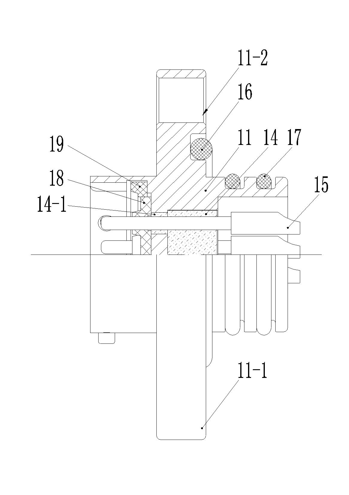
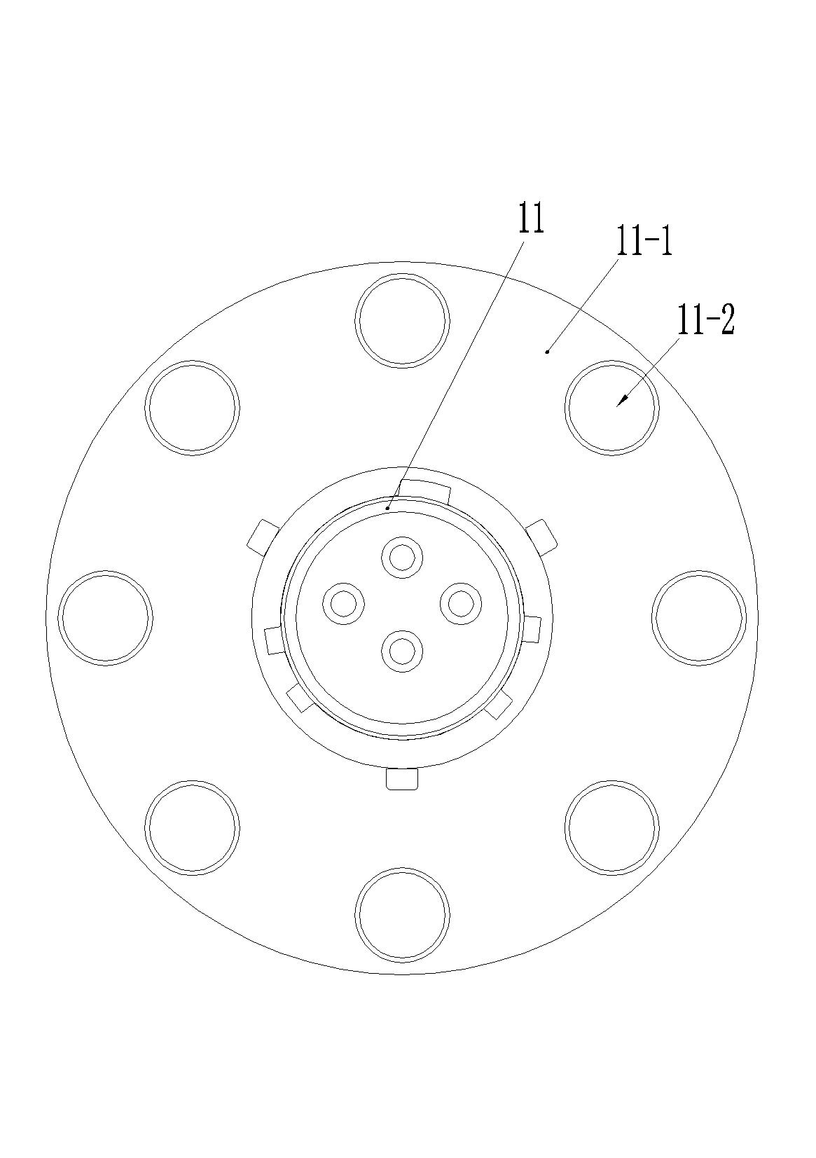
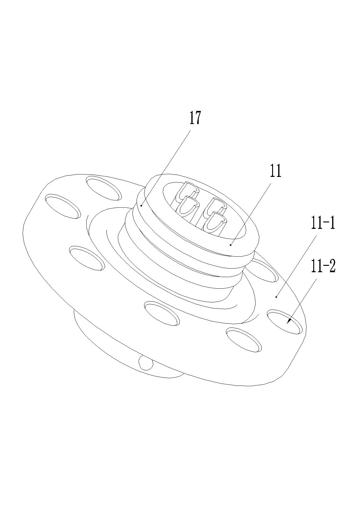
[0016] Embodiment 1 of the high pressure resistant sintered sealed electrical connector of the present invention, as Figure 1-4 As shown, it includes a metal shell 11. In this embodiment, the metal shell 11 is cylindrical, and its outer peripheral surface is provided with an eversion edge 11-1, and an eversion edge 11-1 is provided with a bolt connection hole. At this time, the metal shell 11 can be fixed on the corresponding installation panel 13 by penetrating the screw 12 in the bolt connection hole. The contact piece 15 is fixed in the metal shell 11 by sintering the glass cake 14. In addition, the metal shell 11 A pressure-receiving wall 11-2 is arranged between its two ends. The pressure-receiving wall 11-2 is integrated with the metal shell 11 and is located between the two ends of the contact. The pressure-receiving wall has a passage for the contact to pass through. The outer peripheral surface of the glass cake 14 is sintered and fixed with the inner wall of the met...


PUM


Abstract

The invention relates to a sintered and sealed electric connector resistant to high pressure. The sintered and sealed electric connector comprises a metal shell, wherein a contact element is assembled inside the metal shell by a glass cake; the periphery of the glass cake is sintered and fixed with an internal wall surface of the metal shell; a bearing wall matched with the contact element in an insulating manner is integrally arranged between two ends of the contact element inside the metal shell; a through hole for the contact element to penetrate is formed in the bearing wall; the bearing wall is provided with an interface sealing body on one side adjacent to a plugging end of the electric connector, and the other side of the bearing wall is sintered and fixed with the glass cake; no matter which end of the connector is pressed, the bearing wall can share the pressure, so that the bearable pressure of the connector is not limited by the bonding strength between the glass cake and the shell any more; additionally, the adoption of the glass cake sintering is easier to guarantee the sintering quality in comparison with a glass tube sintering way, thereby solving the problem of poor pressure resistance performance of the prior electric connector adopting a sintered glass insulator on the primise of guaranteeing the sintering quality of the sintered glass insulator.

Description

technical field [0001] The invention relates to the field of electrical connectors, in particular to a high-voltage sintered sealed electrical connector. Background technique [0002] Electrical connectors using sintered glass insulators have been widely used for their good sealing performance and compression resistance. There are two main combinations of the metal shell and the sintered glass insulator of the existing electrical connector using sintered glass. One is to sinter all the contacts in the metal shell with the same glass cake. After sintering, the sintered glass The insulator is only bonded to the inner wall of the metal shell through its outer peripheral surface. In this case, the bonding force between the glass and the metal is limited, and the force F=P*S on the cross section of the entire sintered glass insulator (P represents pressure, S Indicates the cross-sectional area of ​​the sintered glass insulator) must be borne by the bonding force between the oute...

Claims


Application Information

Patent Timeline
Patent Type & Authority Applications(China)
IPC IPC(8): H01R13/52H01R13/516
Inventor 田建朝
Owner CHINA AVIATION OPTICAL-ELECTRICAL TECH CO LTD
Why Eureka
Try Eureka