Image splicing method based on minimum mean square error criterion

A minimum mean square error, image stitching technology, applied in the field of image processing, can solve problems such as affecting visual effects, and achieve the effect of improving stitching quality, eliminating stitching marks, and avoiding cracks

Active Publication Date: 2014-06-04
HARBIN INST OF TECH
View PDF3 Cites 0 Cited by
  • Summary
  • Abstract
  • Description
  • Claims
  • Application Information

AI Technical Summary

Problems solved by technology

Therefore, in the stitching process of two high-resolution images, it is impossible to find the ideal coincident pixel area in the border overlapping area of ​​the two images, so there are obvious stitching marks or cracks, which affect the visual effect

Method used


Image

  • Image splicing method based on minimum mean square error criterion
  • Image splicing method based on minimum mean square error criterion
  • Image splicing method based on minimum mean square error criterion

Examples


specific Embodiment approach 1

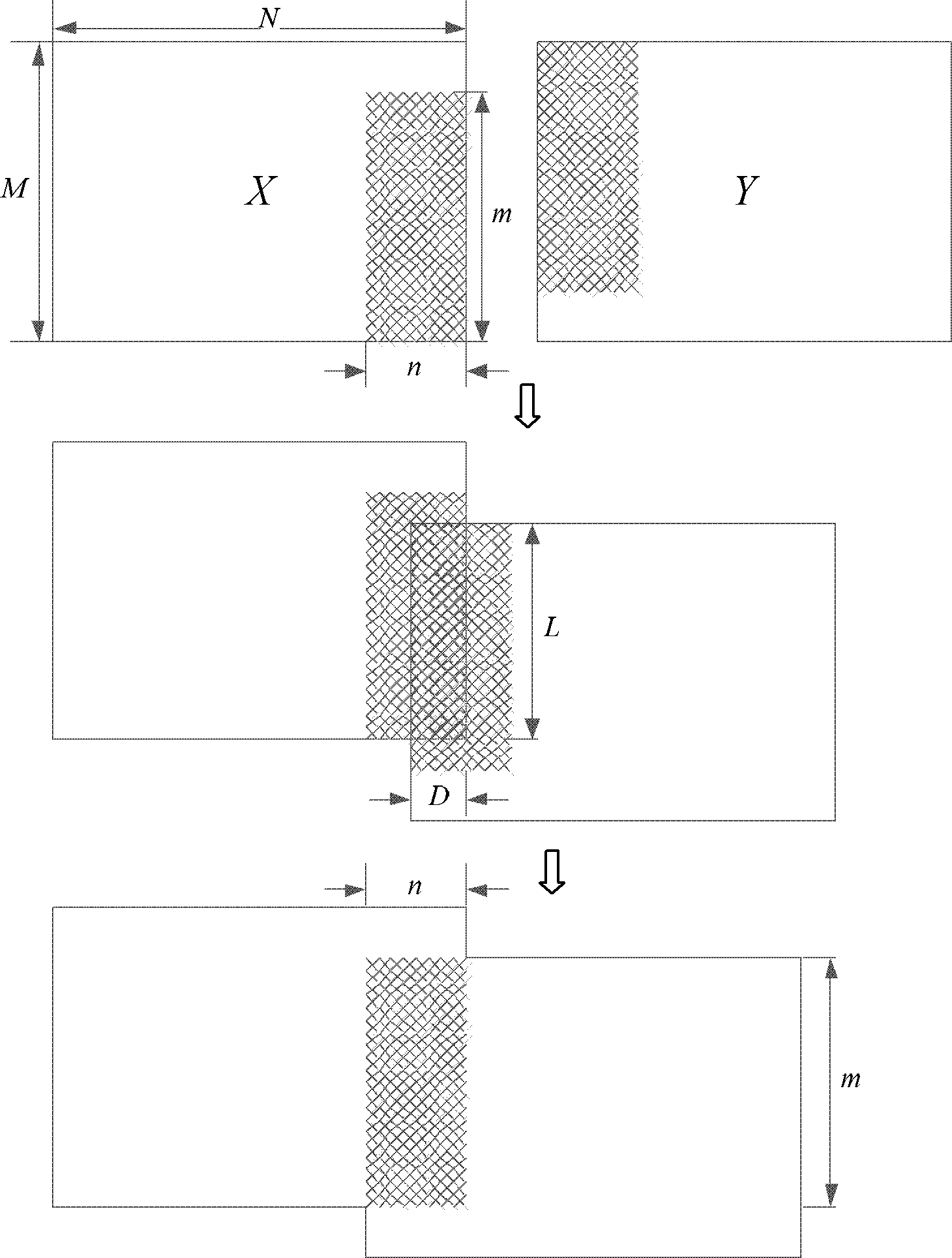
[0022] Specific implementation mode one: as Figure 1~3 As shown, an image mosaic method based on the minimum mean square error criterion described in this embodiment: two images X and Y with a resolution of M×N are set to be mosaiced, and the best overlapping area is an m×n area; set the format of these two images as black and white BMP files, and the range of pixel values ​​is X i,j , Y i,j ∈ {0,...,255}, (i=0, 1...M-1, j=0, 1...N-1); take the upper left corner of the image as X 0,0 , with an X in the lower right corner M-1,N-1 , then the best coincidence area can be expressed in X and Y as: X M-m:M-1,N-n:N-1 and Y 0:m-1,0:n-1 ;

[0023] Said method is realized according to the following steps:

[0024] Step 1. Coarse registration: Coarse registration is completed on the splicing area of ​​image X and Y, and the sliding range of the image splicing area is initially determined as:

[0025] X M ...

specific Embodiment approach 2

[0038] Specific implementation mode two: as image 3 As shown, in this embodiment, the specific process of the area ratio Gaussian transition described in step five is:

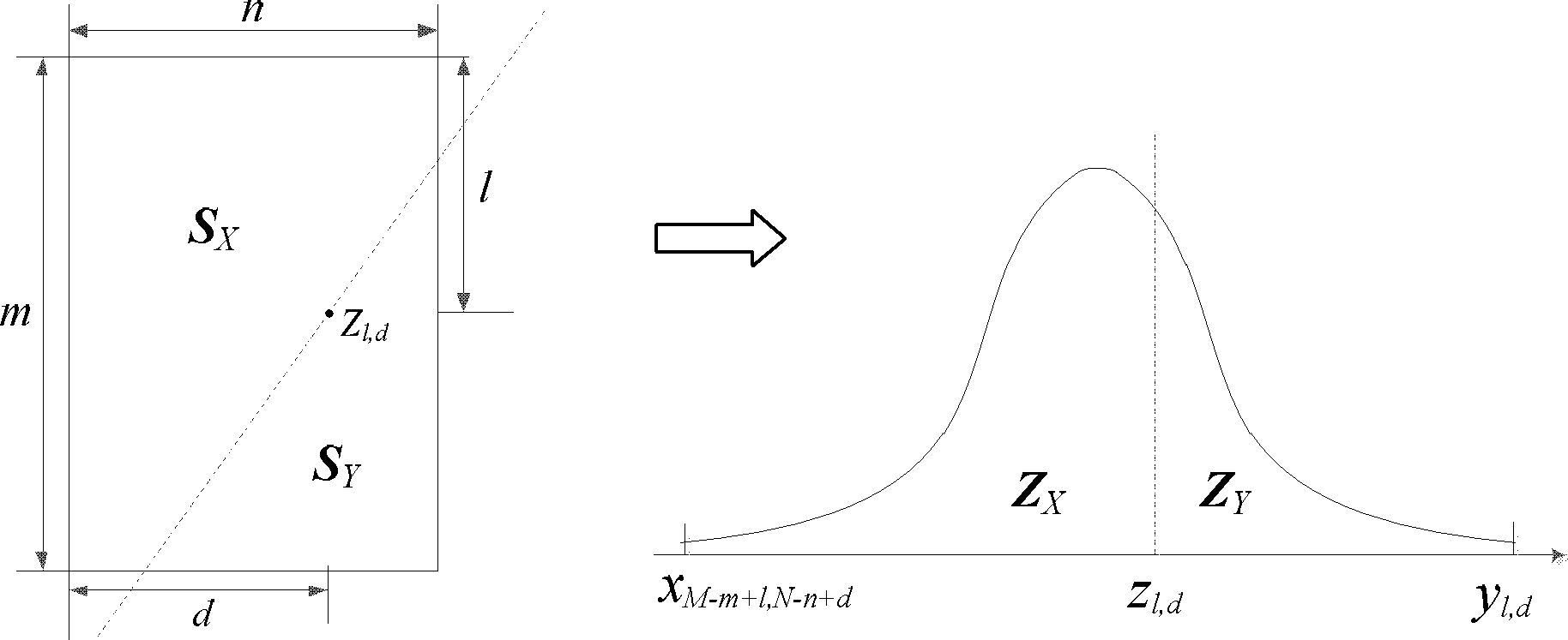
[0039] Step 5 (1), define the overlapping area Z m×n The pixel point on is Z l,d , and the pixel values ​​of the corresponding pixel points in images X and Y are respectively x M-m+l,N-n+d and y l,d ; Pass through the pixel point Z l,d Make a dividing line with a slope of m / n, and the area of ​​the upper left area of ​​the dividing line is S X , the area of ​​the lower right area of ​​the dividing line is S Y ; At this time, the area ratio of the boundary line is S X / S Y ;

[0040] Step 5 (2), use the Gaussian model transition to make the brightness transition of the image stitching area smoother, and find the corresponding pixel value z in the Gaussian distribution map l,d , so that z l,d Left area Z X and the right area Z Y Satisfy:

[0041] Z X / Z Y →S X / S Y (4)

[0042] In ...


PUM


Abstract

The invention provides an image splicing method based on a minimum mean square error criterion, relating to a high precision image splicing method, belonging to the field of image processing technology. A purpose of the invention is applying the minimum mean square error criterion to realize the registration of best overlap regions with high accuracy. The method comprises the following steps of: carrying out rough registration; sliding a registration area; calculating epsilon [L*D], sliding an image splicing area around a rough registration splicing range, and calculating the mean square error value epsilon [L*D] of an overlapping area successively; carrying out epsilon [min] updating, updating a large value with a minimum mean square error, and recording a corresponding overlapping area; repeating the operation in a sliding range, wherein when L is not equal to m or D is not equal to n, epsilon [L*D] is larger than epsilon [opt]; when a mean square error of an examine overlapping area shows an obvious valley, expressing an area reaching a minimum pixel difference, and finally using the overlapping area corresponding to the minimum mean square error epsilon [min]= epsilon [opt] as an optimal overlapping area X[M-m:M-1,N-n:n-1] and Y[0:m-1,0:n-1] of registration; and carrying out area ratio Gauss transition. The method is suitable for the image splicing of two-dimensional planar graphs with a same pixel density degree, and is applied to splicing of continuously shot images of a same image acquisition device.

Description

technical field [0001] The invention relates to a high-precision image splicing method, which belongs to the technical field of image processing. Background technique [0002] As an important branch of image processing technology, image stitching is used in various fields that require high-resolution or wide-angle images. With the current image acquisition technology, there will be slight differences in image brightness due to different acquisition angles. Therefore, during the splicing process of two high-resolution images, it is impossible to find an ideally coincident pixel point area in the border overlapping area of ​​the two images, thus leaving obvious splicing marks or cracks, which affect the visual effect. Image stitching includes two processes of image registration and image fusion. The method of image registration commonly used at present is the method of extracting feature points. Contents of the invention [0003] The purpose of the present invention is to...

Claims


Application Information

Patent Timeline
Patent Type & Authority Patents(China)
IPC IPC(8): G06T5/50
Inventor 沙学军王焜房宵杰吴宣利吴玮白旭高玉龙
Owner HARBIN INST OF TECH
Why Eureka
Try Eureka