
High-resolution photoelectric imaging detection system of space target in daytime

A high-resolution image and space target technology, which is applied in the field of high-resolution imaging output terminals and high-resolution photoelectric imaging detection systems for space targets during the day, can solve the problem of low observation efficiency of ground-based photoelectric imaging terminals, resolution that cannot reach the diffraction limit, Complicated system structure and other problems, to achieve the effect of suppressing high-brightness sky background, low maintenance cost, and strong detection ability

Active Publication Date: 2012-09-12
CHANGCHUN INST OF OPTICS FINE MECHANICS & PHYSICS CHINESE ACAD OF SCI
View PDF2 Cites 26 Cited by
  • Summary
  • Abstract
  • Description
  • Claims
  • Application Information

AI Technical Summary

Problems solved by technology

[0005] In order to solve the problems that the resolution of the existing imaging technology cannot reach the diffraction limit, the high-resolution imaging of space objects in the daytime is seriously polluted by the atmosphere, the observation efficiency of the ground-based photoelectric imaging terminal is low, and the system structure is complex, etc., the purpose of the present invention is to provide a A daytime high-resolution photoelectric imaging detection system for space targets, based on the phase difference speckle method, is especially suitable for space target tracking, detection and high-resolution imaging during the daytime, which can effectively suppress the high-brightness sky background and stray light during the daytime, and overcome Influence of Strong Turbulent Atmospheric Disturbance on High Resolution Imaging

Method used


Image

  • High-resolution photoelectric imaging detection system of space target in daytime
  • High-resolution photoelectric imaging detection system of space target in daytime
  • High-resolution photoelectric imaging detection system of space target in daytime

Examples


Embodiment Construction

[0012] The specific implementation manners of the present invention will be described in further detail below in conjunction with the accompanying drawings.

[0013] This embodiment is carried out on the premise of the technical solution of the present invention, and the detailed implementation and specific operation process are given, but the protection scope of the present invention is not limited to the following embodiments.

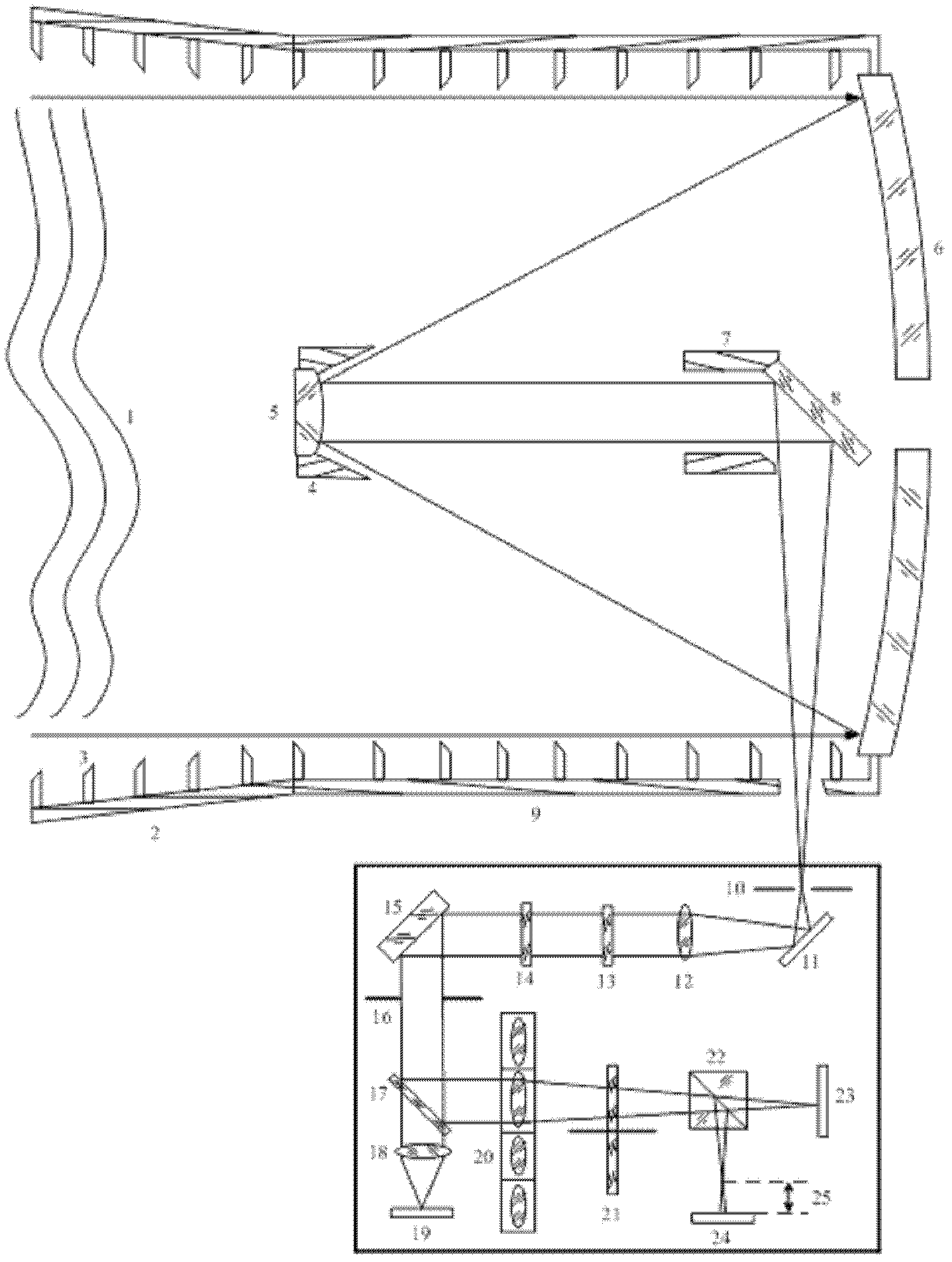
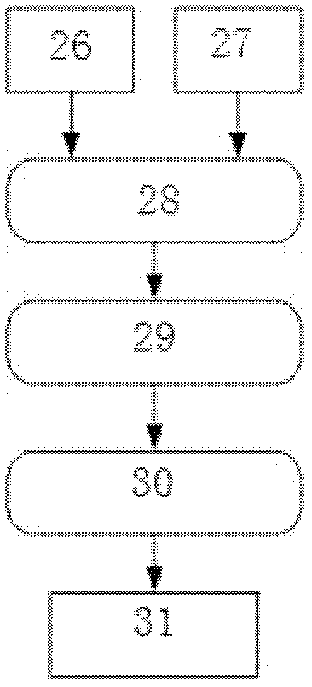
[0014] Depend on figure 1 and figure 2 As shown, the daytime high-resolution photoelectric imaging detection system for space targets includes two parts: an optical system and a phase difference high-resolution image processing unit. The optical system includes a wavefront 1 subject to atmospheric disturbance, a primary mirror 6, a secondary 5. Secondary mirror hood 4, third mirror 8, third mirror hood 7, outer light hood 2, light blocking ring 3, lens barrel hood 9, field diaphragm 10, folding mirror 11, collimating mirror group 12 , Polarizer 13...


PUM


Abstract

The invention discloses a high-resolution photoelectric imaging detection system of a space target in the daytime, which relates to the field of the photoelectric detection and recognition of space targets, in particular to a high-resolution imaging scheme which integrates an optical design with a phase difference image restoration technology; a path of out-of-focus imaging channel is additionally arranged through a beam splitter prism and the defocusing amount of the out-of-focus channel is known and predicable; and the image and the calculating wavefront phase information of the space target which is polluted by strong turbulent atmosphere in the daytime is jointly restored through a phase difference speckle method by acquiring the double-channel multi-frame short exposure images of the focus plane and the out-of-focus plane of the same space target at the same time. The problems of the capture and the detection of the space target in the daytime as well as the problems of the elimination of strong stray light and the suppression of high-brightness sky background are solved. The system has the advantages of simple structure, low design and production cost, low maintenance cost, strong detection capability and the like.

Description

technical field [0001] The invention relates to a daytime high-resolution photoelectric imaging detection system for space objects, which can be applied to a high-resolution imaging output terminal of a ground-based large-scale photoelectric telescopic system with a diameter of 1 m or more, and belongs to the technical field of photoelectric detection and identification of space objects. Background technique [0002] The high-resolution imaging technology of ground-based photoelectric telescopes can realize the monitoring and detailed inspection of space targets and other targets, which is of great significance to the situational awareness of space targets. However, the resolution of ground-based large-aperture telescopes cannot reach the diffraction limit due to the limitation of atmospheric disturbances. For example, if a telescope with an aperture of 5m works in a general plain area, its resolution will not be higher than that of a telescope with an aperture of 0.1-0.2m d...

Claims


Application Information

Patent Timeline
IPC IPC(8): G01S17/89G01S7/495G01J9/00G02B23/00
Inventor 王建立王斌刘莹奇汪宗洋赵金宇
Owner CHANGCHUN INST OF OPTICS FINE MECHANICS & PHYSICS CHINESE ACAD OF SCI
Learn More