
Multiple-degree-of-freedom near-field optical microscope based on micro-nano motion arm

A near-field optics and manipulator technology, applied in the field of nano optics, can solve the problems of slow imaging speed, large volume, and small imaging depth of field, and achieve the effects of accurate measurement and imaging, large moving scale, and wide imaging range

Active Publication Date: 2012-09-12
INST OF SEMICONDUCTORS - CHINESE ACAD OF SCI
View PDF5 Cites 15 Cited by
  • Summary
  • Abstract
  • Description
  • Claims
  • Application Information

AI Technical Summary

Problems solved by technology

At present, commercial scanning near-field optical microscopes generally have problems such as large size and inflexible manipulation. Therefore, when integrating with other technologies and equipment, it is necessary to improve its flexibility and maneuverability
In addition, when performing dynamic detection of nanomaterials and devices, the existing scanning near-field optical microscope has slow imaging speed, low efficiency of searching and positioning samples, and the imaging depth of field is extremely small (only surface topography can be obtained), so it is impossible to analyze the structure. Imaging of samples with large undulations, which hinders the promotion of its application range

Method used


Image

  • Multiple-degree-of-freedom near-field optical microscope based on micro-nano motion arm
  • Multiple-degree-of-freedom near-field optical microscope based on micro-nano motion arm
  • Multiple-degree-of-freedom near-field optical microscope based on micro-nano motion arm

Examples


Embodiment Construction

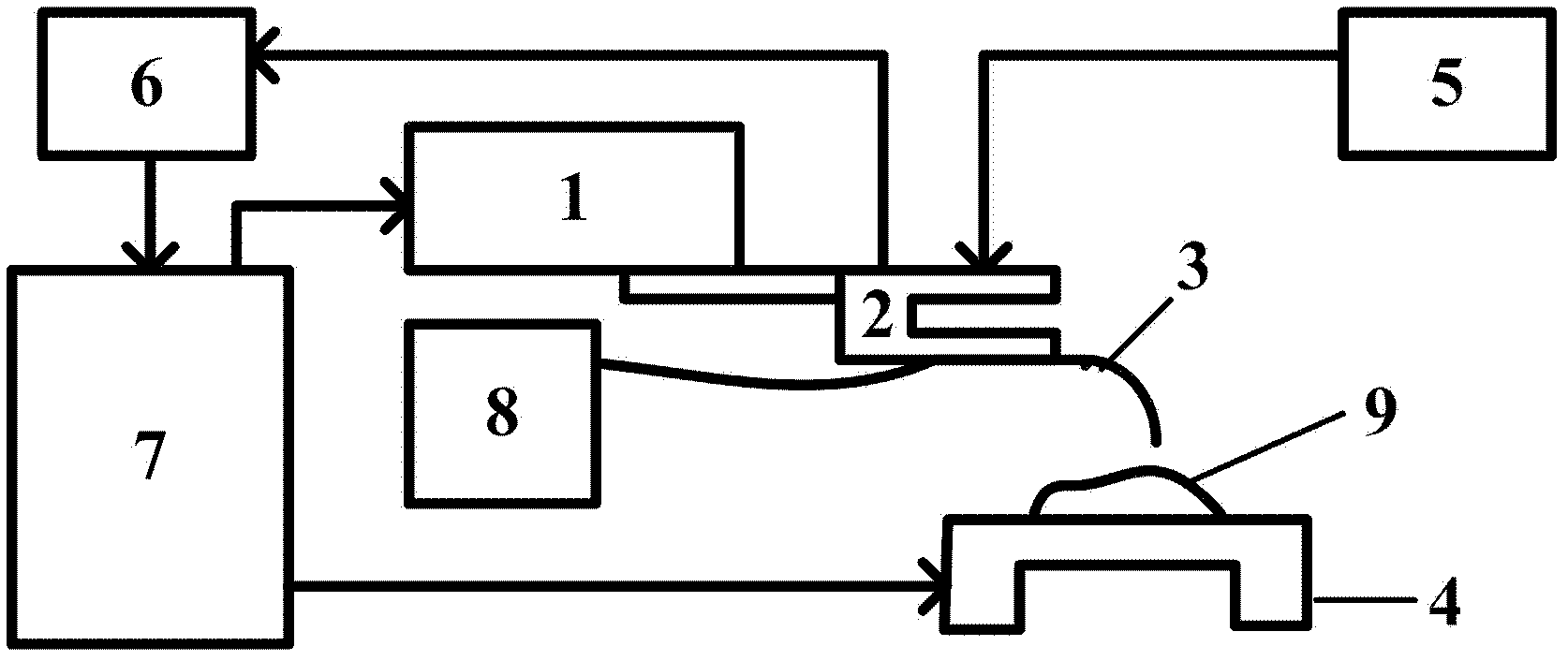
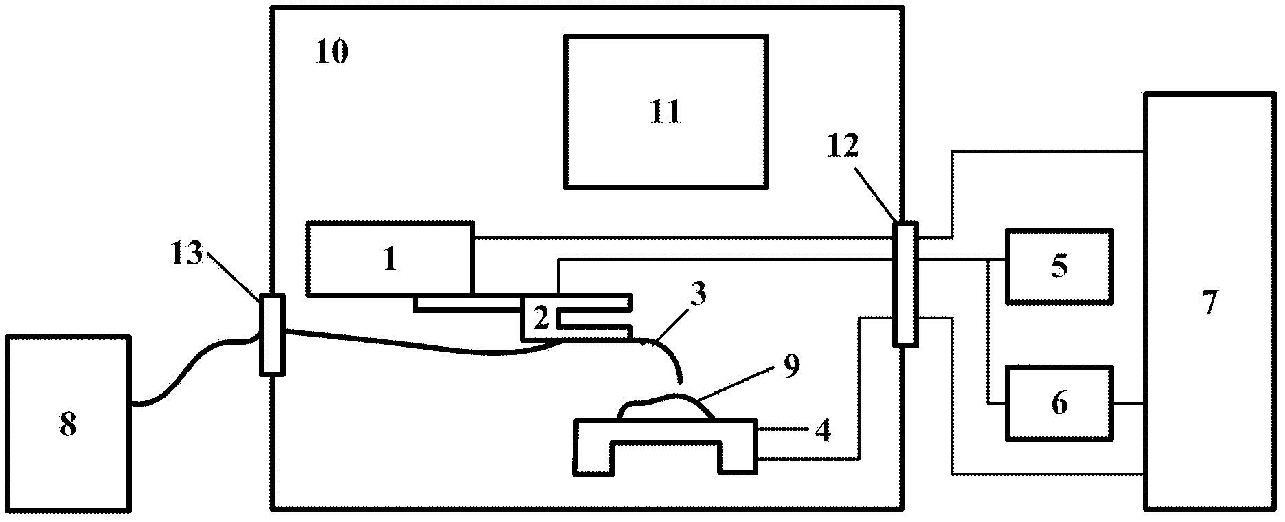
[0022] see figure 1 As shown, the present invention provides a multi-degree-of-freedom near-field optical microscope based on a micro-nano manipulator, including:

[0023] A micro-nano manipulator 1;

[0024] A quartz tuning fork 2, the quartz tuning fork 2 is fixed on the front end of the micro-nano operating arm 1, the quartz tuning fork 2 includes two tuning fork arms and an input end and an output end;

[0025] A near-field optical fiber probe 3, the near-field optical fiber probe 3 is fixed on a tuning fork arm 91 of the quartz tuning fork 2, wherein the material of the near-field optical fiber probe 3 is a quartz optical fiber, and the wavelength of light passing through the probe is 400nm-1600nm. Tip size less than 200nm;

[0026] A sample scanning table 4, the sample scanning table 4 is located below the quartz tuning fork 2, and the sample scanning table 4 is a three-dimensional piezoelectric ceramic scanning table;

[0027] A sinusoidal signal generator 5, the sig...


PUM


Abstract

A multiple-degree-of-freedom near-field optical microscope based on a micro-nano motion arm comprises the micro-nano motion arm, a quartz tuning fork, a near-field optical probe, a sample scanning stand, a sinusoidal signal generator, a preposed lock-in amplifier, a control box and a detector and / or a light source, wherein the quartz tuning fork is fixed at the front end of the micro-nano motion arm; the near-field optical probe is fixed on one tuning fork arm of the quartz tuning fork; the sample scanning stand is positioned under the quartz tuning fork; the signal output end of the sinusoidal signal generator is connected with the input end of the quartz tuning fork; the input end of the preposed lock-in amplifier is connected with the output end of the quartz tuning fork; the input end of the control box is connected with the output end of the preposed lock-in amplifier, one output end of the control box is connected with the input end of the micro-nano motion arm, and the other output end of the control box is connected with the input end of the sample scanning stand; and the detector and / or the light source are / is connected with the near-field optical probe. The multiple-degree-of-freedom near-field optical microscope has an optical resolution capability beyond the diffraction limit as well as large-scale mobile flexibility and multi-degree-of-freedom operation capability, occupies a small space, and is very convenient to be combined with other microscopic characterization methods.

Description

technical field [0001] The invention relates to the field of nano-optic technology, in particular to a multi-degree-of-freedom near-field optical microscope based on a micro-nano manipulator. Background technique [0002] The research of nano-optics poses a series of new challenges to optical technology. For example, in the field of optical imaging, it is required to observe smaller details, in the field of optical storage, it is required to generate smaller recording points, in the field of optical manipulation, it is required to capture finer particles, In the field of spectroscopic detection requires the study of finer structures and so on. The fundamental requirement of these challenges is to improve the optical resolution, but the diffraction limit severely restricts the development of this process. There has been a long history of exploring breakthroughs in the optical diffraction limit. It was not until the invention of the scanning probe microscope at the end of the...

Claims


Application Information

Patent Timeline
IPC IPC(8): G01Q60/18
Inventor 王瑞谢亮祝宁华
Owner INST OF SEMICONDUCTORS - CHINESE ACAD OF SCI
Learn More