
Bladeless fan

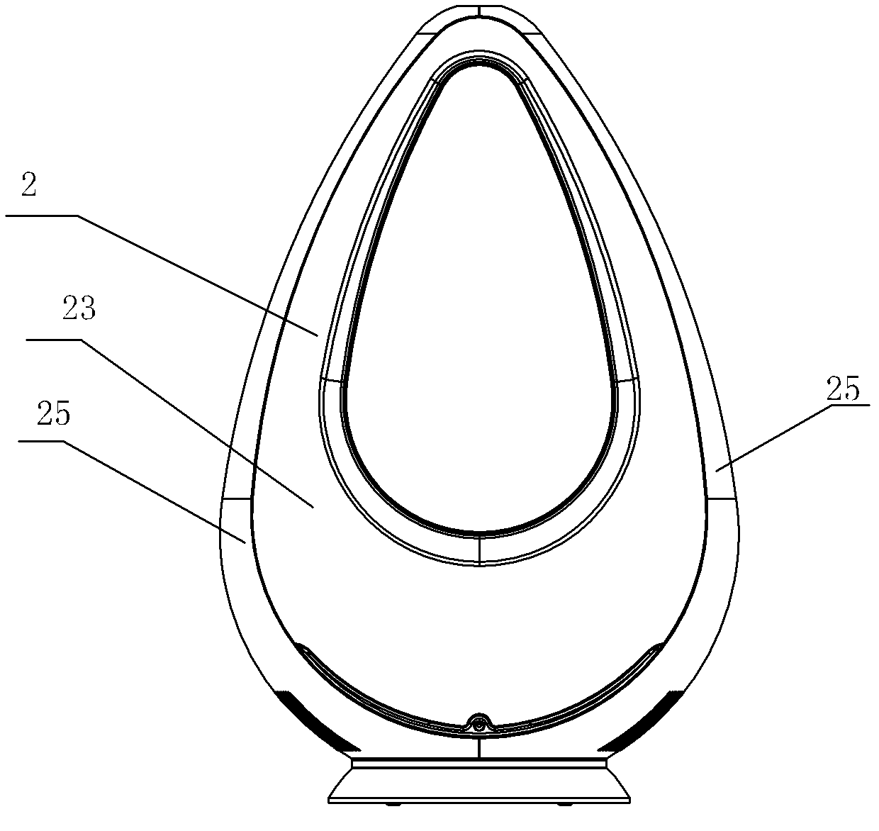
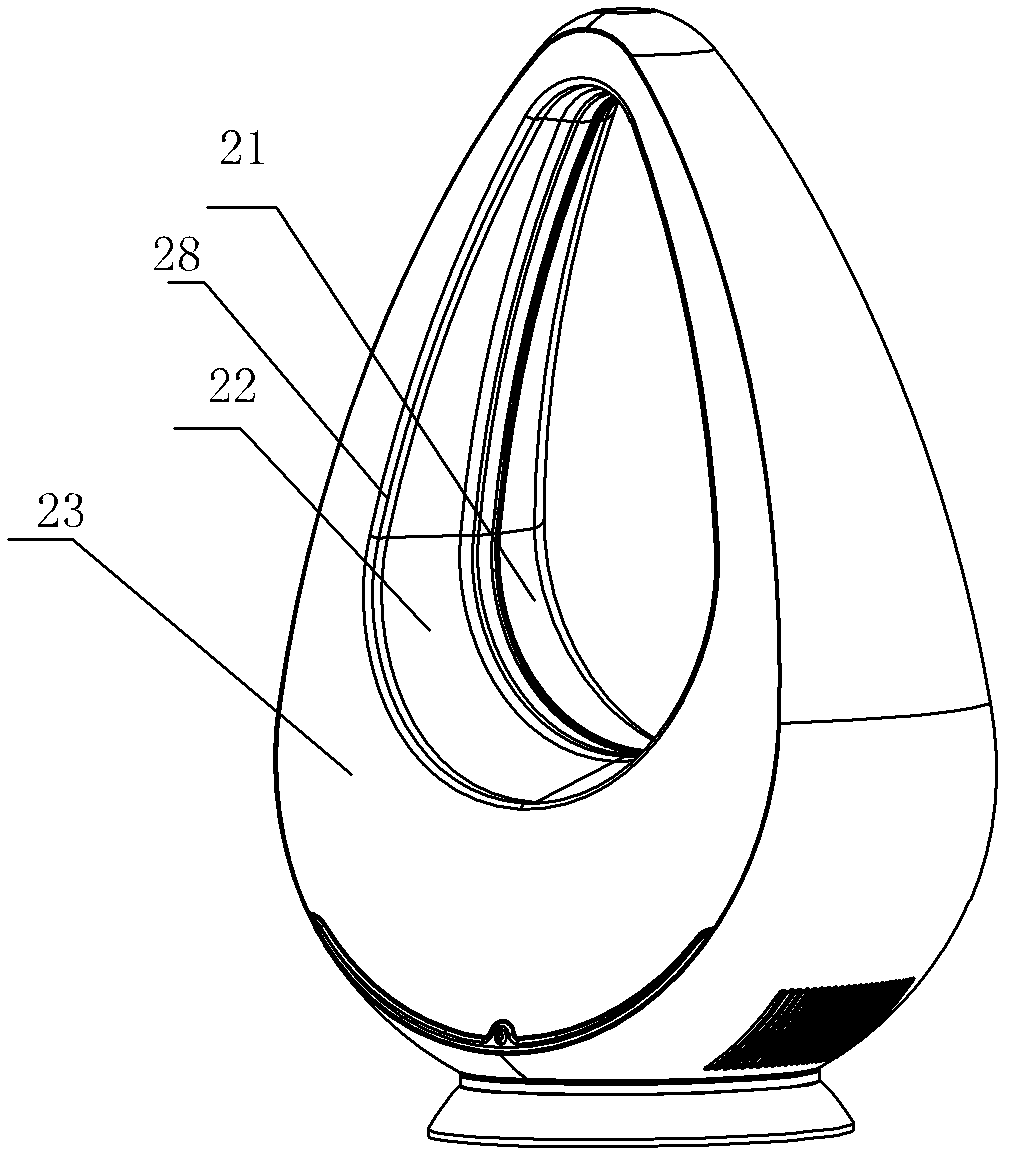
A bladeless fan and air nozzle technology, applied in the field of electric fans, can solve problems such as uneven wind speed, large flow, and loud noise, and achieve the effect of uniform wind speed, low noise, and noise elimination

Active Publication Date: 2012-09-12
NINGBO HANMING TECHNOLOGY CO LTD
View PDF9 Cites 14 Cited by
  • Summary
  • Abstract
  • Description
  • Claims
  • Application Information

AI Technical Summary

Problems solved by technology

The nozzle is an annular nozzle, but according to the Coanda effect of Coanda and the Bernoulli equation wp=0.5·ro·v2, the airflow in the annular nozzle has the characteristic of upward flow, so that the pressure of the airflow gradually increases from bottom to top in the annular nozzle. Increase, the airflow ejected from the mouth will have a large flow difference from bottom to top, resulting in uneven wind speed ejected from the annular nozzle, the upper wind speed of the annular nozzle is relatively large, and the lower wind speed of the annular nozzle is relatively small
At the same time, the high-speed airflow of the annular nozzle produces a large noise

Method used


Image

  • Bladeless fan
  • Bladeless fan
  • Bladeless fan

Examples


Embodiment Construction

[0031] The present invention will be further described in detail below in conjunction with the accompanying drawings and embodiments.

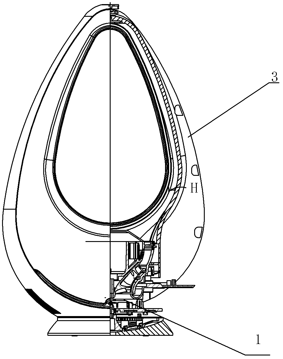
[0032] A bladeless fan, comprising a device 1 for forming airflow and an annular nozzle 2, the annular nozzle 2 includes an annular cavity 3 and an opening 4 for emitting airflow, an isolation cover assembly 5 is arranged in the annular cavity 3, and the isolation The cover assembly 5 divides the annular cavity into an outer annular cavity 6 and an inner annular channel 7 for receiving airflow. The cross-sectional area of ​​the inner annular channel 7 gradually becomes smaller from bottom to top, and the outer annular cavity 6 is provided with a sound-absorbing Cotton8.

[0033] Depend on Figure 5 , Image 6 It can be seen that the width W of the inner annular channel 7 gradually narrows from bottom to top, and the thickness H of the inner annular channel 7 gradually decreases from bottom to top, so that the overall shape of the inner annul...


PUM


Abstract

The invention discloses a bladeless fan, which comprises a device for forming an air flow and an annular spray nozzle. The annular spray nozzle includes an annular cavity and an opening for air flow jetting. In the annular cavity is arranged an isolation cover assembly which divides the annular cavity into an outer annular cavity and an inner annular channel for receiving the air flow, the cross sectional area of the inner annular channel gradually decreases from bottom up, and silencer cotton is arranged in the outer annular cavity. According to the characteristics of a high pressure air flow, the high pressure air flow at the lower part of the annular channel of an electric fan in prior arts gathers around the upper part of the annular channel from bottom up, while the inventive inner annular channel has the cross sectional area gradually decreasing from bottom up to realize uniform air pressure in the inner annular channel, so that the velocity of the air flow jetted from the opening is identical and that the velocity of the air from the annular spray nozzle is uniform. The silencer cotton arranged in the outer annular cavity can eliminate noise generated by the high-velocity air flow in the inner annular channel, so that noise is low during electric fan operation.

Description

technical field [0001] The invention relates to an electric fan, in particular to a bladeless fan. Background technique [0002] Compared with traditional electric fans, bladeless electric fans have the characteristics of low noise and good safety. Chinese Patent No. 200990100311.8 discloses a utility model patent named "Bladeless Fan Assembly and Its Nozzle". Its structure includes a device for forming airflow and a nozzle. At the mouth from which the airflow is emitted, the nozzle extends about an axis to define an opening through which air from outside the fan assembly is drawn by the airflow emitted from the mouth, the nozzle including a surface on which the mouth is positioned to For directing airflow, the surface includes a diffuser portion tapered away from the axis and a guide portion downstream of and angled from the diffuser portion. The nozzle is an annular nozzle, but according to the Coanda effect of Coanda and the Bernoulli equation wp=0.5·ro·v2, it can be kn...

Claims


Application Information

Patent Timeline
Patent Type & Authority Applications(China)
IPC IPC(8): F04F5/16F04F5/44
Inventor 魏建峰
Owner NINGBO HANMING TECHNOLOGY CO LTD
Learn More