Eureka AIR delivers breakthrough ideas for toughest innovation challenges, trusted by R&D personnel around the world.

Dust removing device for filter of automobile

A dust removal device and filter technology, which is applied in the direction of fuel air filter, etc., can solve the problems of affecting the health of operators, flying smoke and dust, polluting the environment, etc., and achieves the advantages of simple structure, reducing environmental pollution, and improving the operating environment Effect

Inactive Publication Date: 2012-09-12
赵长营
View PDF8 Cites 5 Cited by
  • Summary
  • Abstract
  • Description
  • Claims
  • Application Information

AI Technical Summary

Problems solved by technology

[0002] At present, the floating dust on the surface of the filter screen on the automobile filter is blown by using a high-pressure air gun to connect the compressed air, and then inserting its nozzle into the filter. environment, and affect the health of the operator

Method used


Image

  • Dust removing device for filter of automobile
  • Dust removing device for filter of automobile
  • Dust removing device for filter of automobile

Examples


Embodiment 1

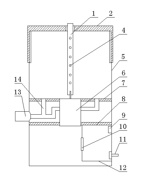
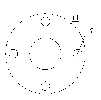
[0018] attached figure 1 Among them, the dust removal mechanism includes a partition 12 arranged on one side below the fixed plate 8, and the partition 12 and the housing 5 form a closed space. An electromagnetic pulse valve 10 is arranged on the partition 12 on one side of the closed space, and a pressure sensor 9 is arranged on the housing 5 on the other side of the closed space, which is connected to the air inlet 11 through a pressure control switch. The partition in this dust removal mechanism is set on one side of the support tube, and its air inlet is connected with compressed air. When in use, after the filter is installed, cover the upper cover, the pressure sensor controls the pressure control switch to open, put in compressed air, when the compressed air reaches a certain value, close the pressure control switch, open the electromagnetic pulse valve, and compress the air Rush out from the electromagnetic pulse valve, quickly enter the filter from the bottom of the ...

Embodiment 2

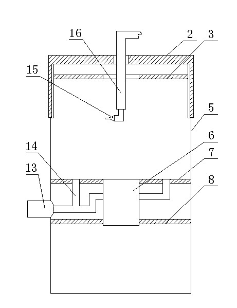
[0021] attached figure 2 Among them, the dust removal mechanism includes a dust-proof plate 3 with a central hole and a compressed gas connecting pipe 16 with a nozzle 15 at the lower end. The compressed gas connecting pipe 16 is flexibly connected with the central hole of the upper cover 2, and the other end of the compressed gas connecting pipe is connected air connection. When in use, install the filter on the support tube, cover the dustproof plate 3, and the dustproof plate 3 is movably connected with the inner wall of the shell 5, that is, the dustproof plate can move up and down with the filter in the shell. Among them, the upper cover is a fully enclosed cover. During the purging process, the upper cover is not covered, only the dustproof plate is covered. Extend the compressed gas connecting pipe into the housing through the center hole of the dust-proof plate, place it in the filter, turn on the compressed air, blow the filter screen from the inside to the outside ...


PUM


Abstract

A dust removing device for a filter of an automobile comprises an upper cover, a shell and a dust removing mechanism. The upper cover and the shell are fastened together, the dust removing mechanism is used for blowing off dust on the filter, a dust removing plate and a fixing plate which are provided with central holes are horizontally arranged in the shell, a supporting barrel used for supporting the filter is arranged between the center hole of the dust removing plate and the center hole of the fixing plate, and is a hollow barrel, dust removing holes are circumferentially arranged on the dust removing plate, and each dust removing hole is communicated with a dust sucking opening on one side of the shell by a dust removing guide tube. The dust removing device is simple in structure, anoperator can clean the filter in an environment without smoke dust, cleaned dust is treated together, environmental pollution is reduced, and the operation environment is improved.

Description

technical field [0001] The invention relates to a dust removal device, in particular to a dust removal device for an automobile filter used for cleaning floating dust on the surface of a filter screen on the automobile filter. Background technique [0002] At present, the floating dust on the surface of the filter screen on the automobile filter is blown by using a high-pressure air gun to connect the compressed air, and then inserting its nozzle into the filter. environment, and affect the health of the operator. Contents of the invention [0003] The invention aims at the defects existing in the existing filter cleaning technology, and provides an automobile filter dust removal device which has a simple structure, closes and cleans the filter and centralizes the dust. [0004] The technical solution adopted to achieve the above invention is: a dust removal device for an automobile filter, the dust removal device includes an upper cover and a housing that are buckled tog...

Claims


Application Information

Patent Timeline
Patent Type & Authority Applications(China)
IPC IPC(8): F02M35/08
Inventor 赵长营
Owner 赵长营
Why Eureka
Eureka Blog
Learn More