Vibrating fruit tree harvester
A vibrating, fruit tree technology, applied in the direction of picking machines, harvesters, agricultural machinery and implements, etc., to achieve the effects of low cost, simple structure and low operation failure rate
- Summary
- Abstract
- Description
- Claims
- Application Information
AI Technical Summary
Problems solved by technology
Method used
Image

Examples
Embodiment 1
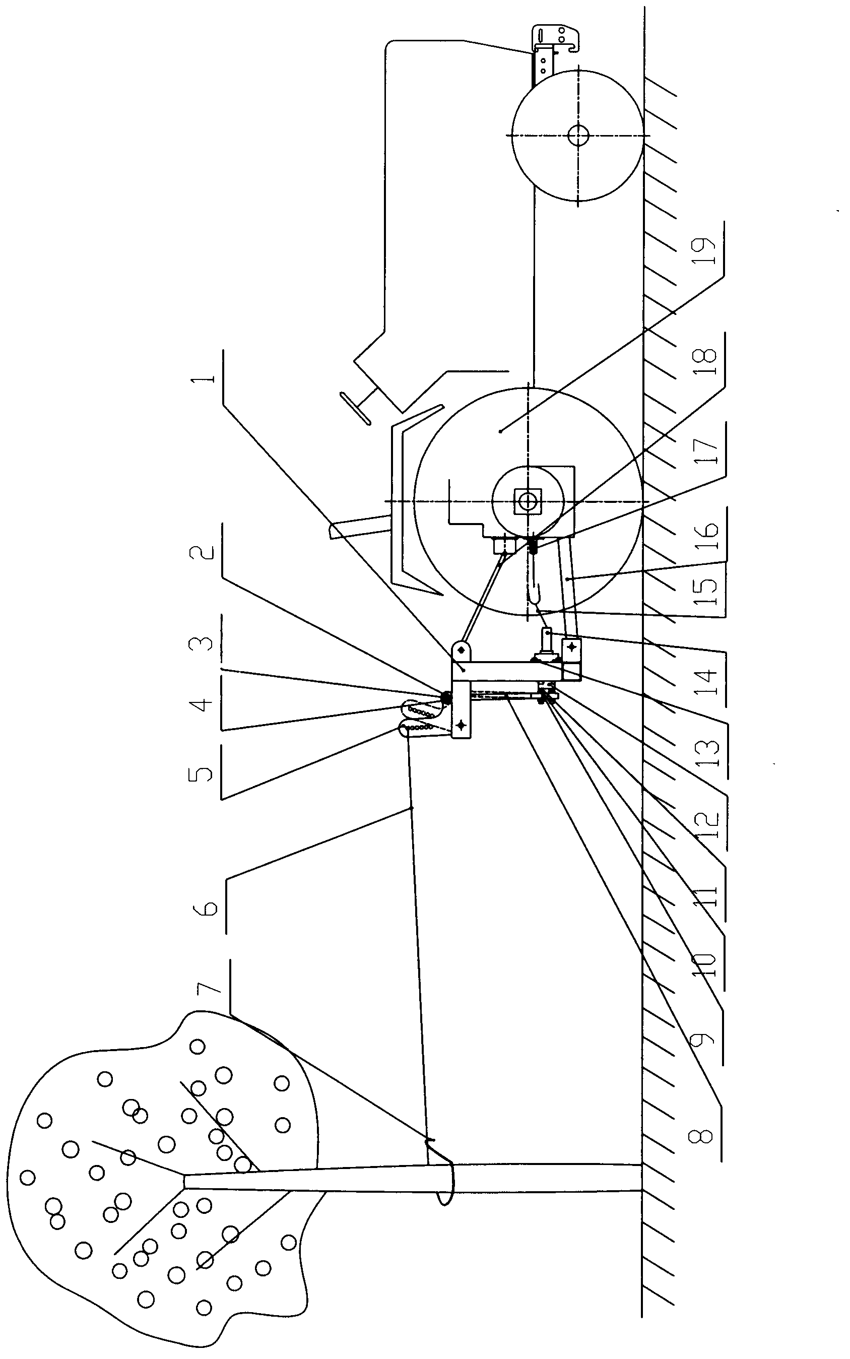
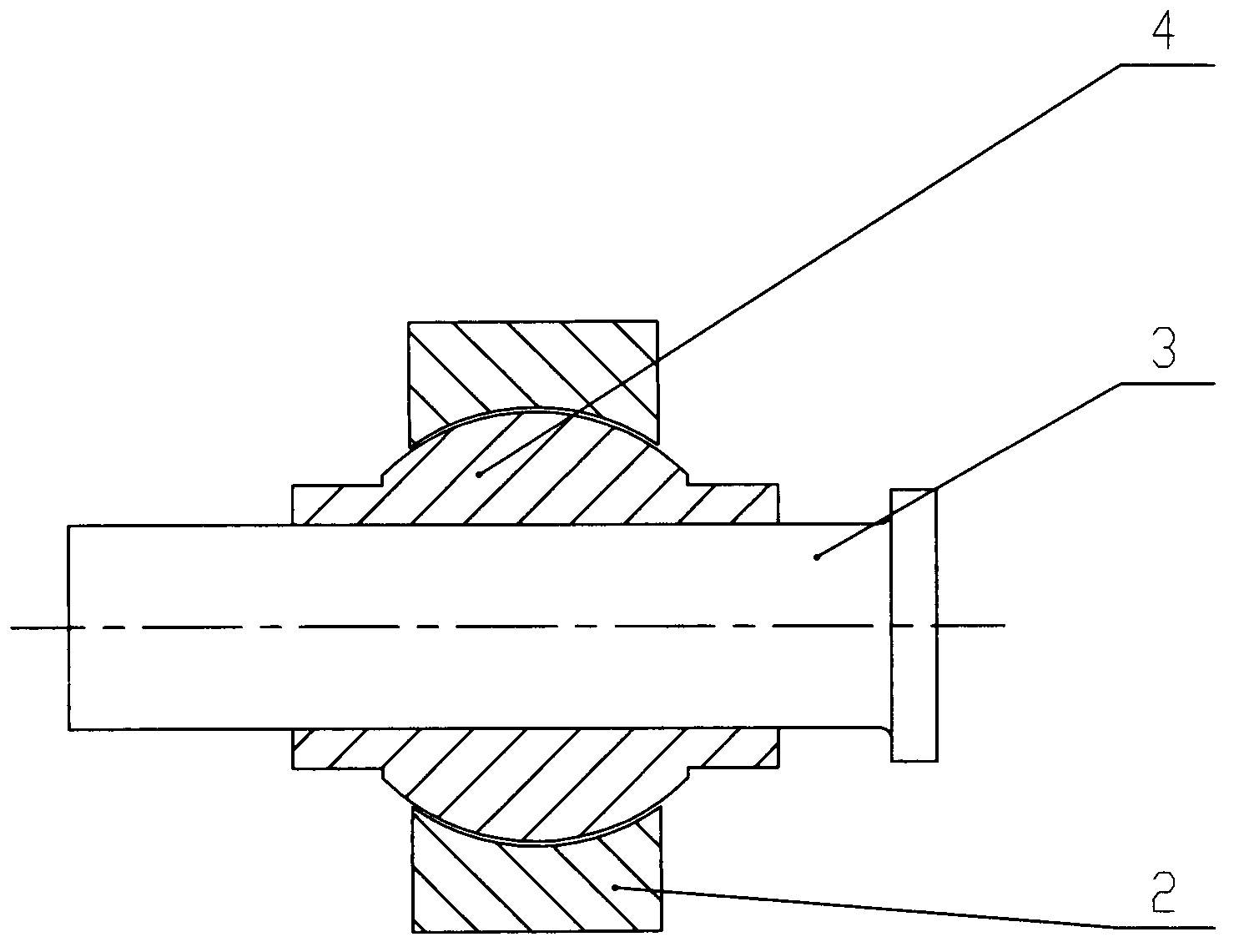
[0017] Embodiment one: the frame (1) is fixed on the rear of the tractor (19) by the lower link (16) and the upper link (18) of the tractor, and the lower link (16) and the upper link (18) of the tractor are hinged with the frame (1) , the height of the frame (1) can be adjusted by controlling the hydraulic lifting system of the tractor (19). The power input shaft (14) is fixed on the frame (1) by a bearing (13), and the other end of the power input shaft (14) is connected to the eccentric wheel (12); the inner spherical pull rod a (2) and the outer spherical bushing a(4) matches and is hinged with the eccentric wheel shaft (11), the eccentric wheel shaft (11) is fixed on the eccentric wheel (12), and the inner spherical pull rod b(9) cooperates with the outer spherical bushing b(10). The pin shaft (3) is hinged to one end of the L-shaped rocker (5), and the other end of the L-shaped rocker (5) is hinged to the rear of the frame (1); the inner spherical pull rod a (2) and the ...
Embodiment 2
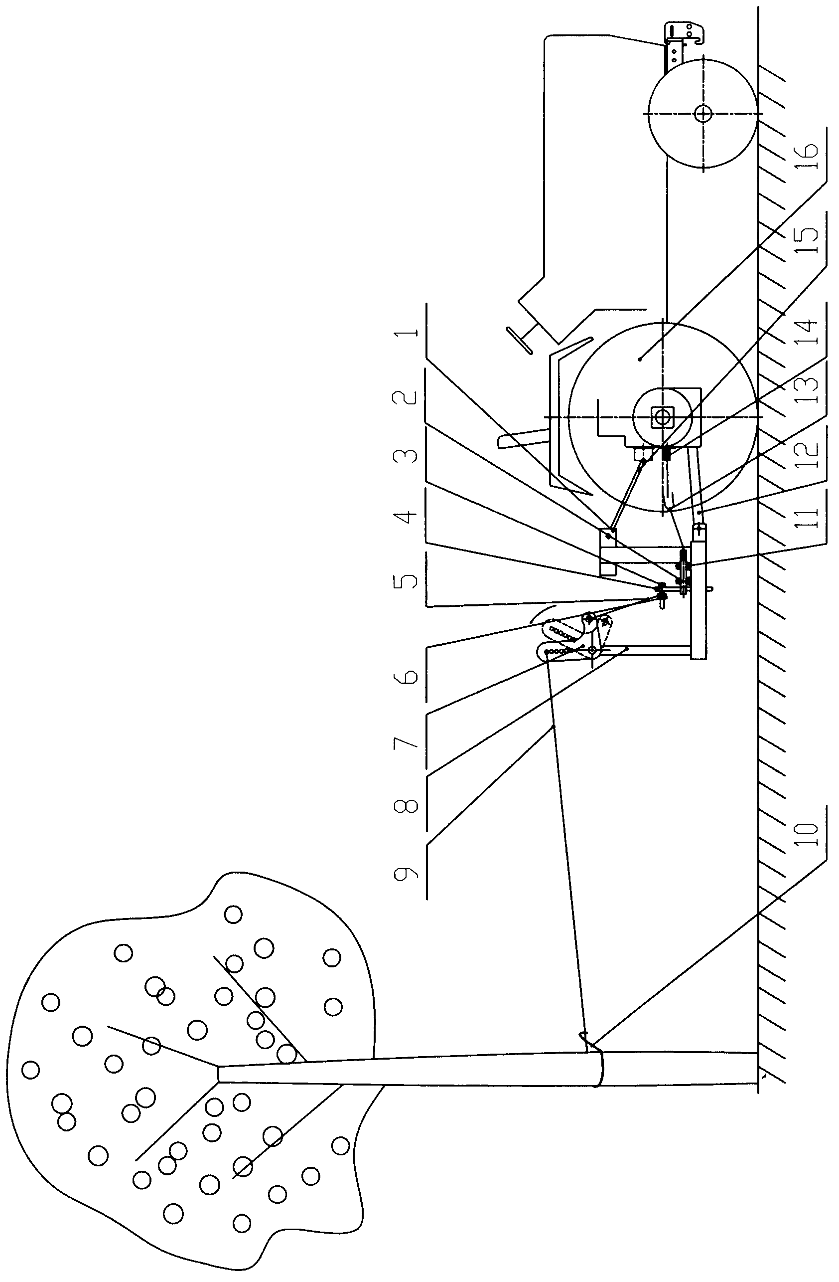
[0018] Embodiment two: the frame (1) is fixed on the rear of the tractor (16) through the lower rod (12) and the upper rod (15), and the eccentric wheel shaft (2) is fixed on the front end of the frame (1) by the bearing with seat (11). The eccentric wheel (4) is fixed on the eccentric wheel shaft (2), and the L-shaped rocker (7) is fixed on the rear end of the frame (1) through the rocker bracket (8); the eccentric wheel (4) is equipped with a connecting rope fixing rod (3) and the collar (6), the collar (6) is hinged with the connecting rope fixed rod (3); the connecting rope (5) connects the L-shaped rocker (7) and the eccentric wheel (4); the L-shaped rocker The left end of the rod (7) is arranged with 1 to 30 round holes from top to bottom, which are used to change the hooking position of the wire rope (9), and the other end of the wire rope (9) is provided with a hook (10); the tractor power output shaft (14 ) drives the eccentric wheel shaft (2) to rotate through the un...
Embodiment 3
[0019] Embodiment three: the frame (1) is fixed on the rear of the tractor (14) through the lower rod (10) and the upper rod (13), the eccentric wheel (4) is fixed on the output shaft of the gear box (3), and the L-shaped rocker (6) Fixed to the rear end of the frame (1) through the rocker bracket (7), the left end of the L-shaped rocker (6) is arranged with 1 to 30 round holes from top to bottom, which are used to change the direction of the wire rope (8). At the hooking position, the other end of the wire rope (8) is provided with a hook (9); the tractor power output shaft (12) is connected with the gearbox input shaft (2) through a universal joint coupling (11); the tractor power output shaft ( 12) The rotation drives the input shaft (2) of the gearbox to rotate, and the input shaft of the gearbox drives the output shaft of the gearbox to rotate, thereby driving the eccentric wheel (4) to rotate. Because one end of the connecting rod (5) is hinged on the eccentric wheel (4)...
PUM
 Abstract
Description
Claims
Application Information
 - Generate Ideas
- Intellectual Property
- Life Sciences
- Materials
- Tech Scout
- Unparalleled Data Quality
- Higher Quality Content
- 60% Fewer Hallucinations
Browse by: Latest US Patents, China's latest patents, Technical Efficacy Thesaurus, Application Domain, Technology Topic, Popular Technical Reports.
© 2025 PatSnap. All rights reserved.Legal|Privacy policy|Modern Slavery Act Transparency Statement|Sitemap|About US| Contact US: help@patsnap.com