Electrically-regulated antenna based on orientation correction and regulation

An electronically adjustable antenna and azimuth correction technology, which is applied to antennas, antenna components, antenna supports/installation devices, etc., can solve problems such as high cost, large errors, and difficulties.

Inactive Publication Date: 2012-09-05
TONGYU COMM INC
View PDF9 Cites 14 Cited by
  • Summary
  • Abstract
  • Description
  • Claims
  • Application Information

AI Technical Summary

Problems solved by technology

[0003] The above characteristics of the electric adjustable antenna determine that in order to realize the precise adjustment of the downtilt angle, it is necessary to ensure the ideal setting of the mechanical inclination angle of the antenna vibrator, otherwise the ideal pattern cannot be obtained only through the adjustment of the electric downtilt angle, which will affect the installation of the antenna. Construction puts forward very high requirements. Usually, it is very difficult to adjust the mechanical inclination angle of the antenna vibrator after the antenna is installed, and the error is large. Both construction and maintenance require high costs, and it is usually not ideal effect; on the other hand, the traditional electronically adjustable antenna can only adjust the electrical downtilt, but cannot adjust the azimuth in the horizontal direction, and it is usually adjusted manually, and the accuracy is very poor
In addition, the downtilt angle can only be adjusted within the range of the signal coverage sector. If it exceeds the range of the signal coverage sector, it can only be solved by adding a new antenna, which is very expensive. By adjusting the horizontal direction of the antenna oscillator Orientation can solve this problem very well

Method used


Image

  • Electrically-regulated antenna based on orientation correction and regulation
  • Electrically-regulated antenna based on orientation correction and regulation
  • Electrically-regulated antenna based on orientation correction and regulation

Examples


Embodiment Construction

[0043] The present invention will be described in further detail below in conjunction with the accompanying drawings and specific implementation examples, but it is not intended to limit the technical solution of the present invention.

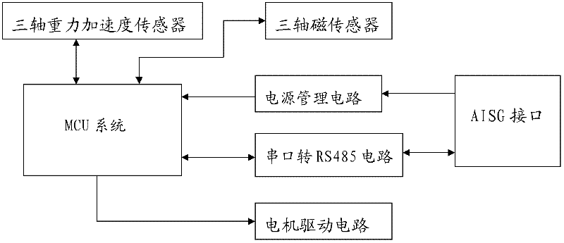
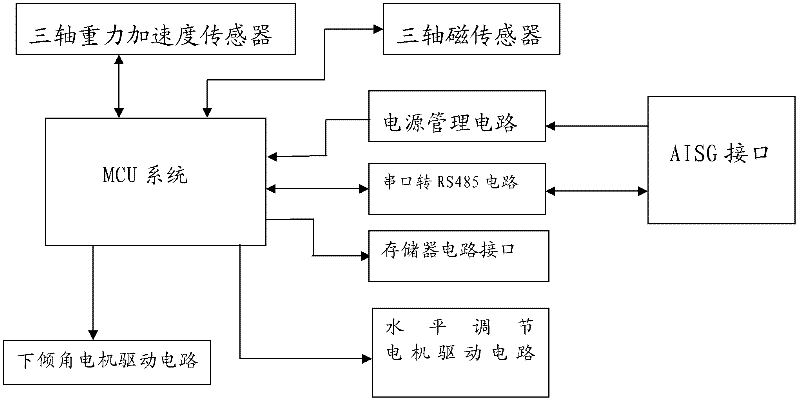
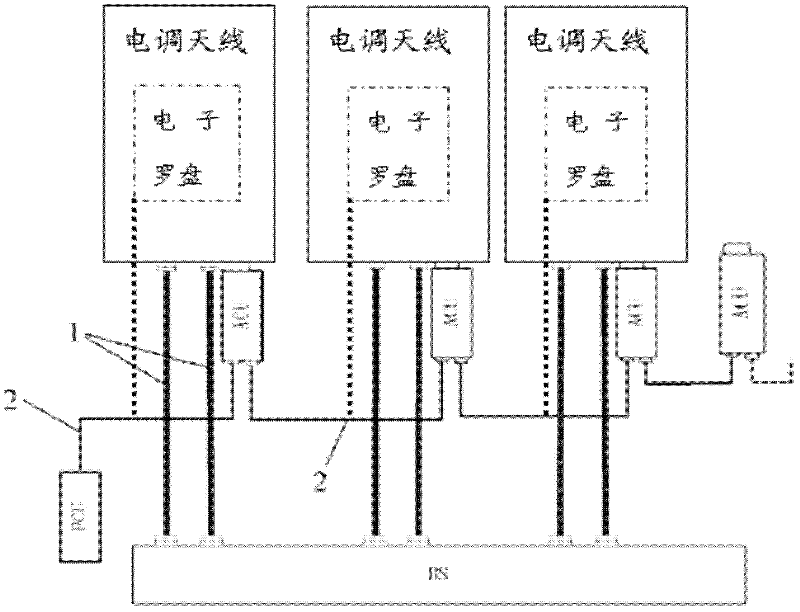
[0044] This embodiment includes: at least one electrically adjustable antenna body, the electrical downtilt and azimuth of the electrically adjustable antenna body are adjustable; at least one antenna control unit is used to adjust the electrical downtilt and azimuth of the electrically adjustable antenna body, It has an input end and an output end, and the output end is electrically connected to the electric adjustable antenna body, and the antenna control unit corresponds to the electric adjustable antenna body one by one; at least one terminal control module, the terminal control module controls connected to the input end of the antenna control unit, and establishes a communication link with the antenna control unit, and each terminal contro...


PUM


Abstract

The invention discloses an electrically-regulated antenna based on orientation correction and regulation, which comprises at least one electrically-regulated antenna body, at least one antenna control unit, at least one terminal control module and a direction sensing device, wherein the downward inclination angle and the azimuthal angle of the electrically-regulated antenna body can be regulated; the at least one antenna control unit is used for regulating the downward inclination angle and the azimuthal angle of the electrically-regulated antenna body and is provided with an input end and an output end, the output end is electrically connected to the electrically-regulated antenna body, and the antenna control unit is corresponding to the electrically-regulated antenna body one by one; the terminal control module controls and is connected to the input end of the antenna control unit, and establishes a communication link with the antenna control unit, and each terminal control module respectively controls one or more antenna control units; and the direction sensing device is fixed on the electrically-regulated antenna body, and used for sensing the physical orientation of the electrically-regulated antenna body, and the direction sensing device is electrically connected to the input end of the antenna control unit.

Description

[technical field] [0001] The invention relates to the field of wireless communication base station antennas, in particular to an optimally designed electrically adjustable antenna with adjustable electrical downtilt and azimuth. [technical background] [0002] The technology of mobile communication base station antennas has developed rapidly. Initially, ordinary directional and omnidirectional antennas were mainly used in China. At present, electronically adjustable antennas are becoming more and more popular. The so-called electronically adjustable antennas refer to base station antennas that can adjust the electronic downtilt angle. The principle of electronic downtilt is to change the phase of the collinear array antenna oscillator, change the amplitude of the vertical component and horizontal component, and change the field strength of the composite component, so that the vertical directivity diagram of the antenna is downtilted. Since the field strength in all direction...

Claims


Application Information

Patent Timeline
Patent Type & Authority Applications(China)
IPC IPC(8): H01Q3/08H01Q1/18
CPCH01Q1/125H01Q1/246H01Q3/005H01Q3/08H01Q1/50H01Q3/00H01Q23/00
Inventor 毛纪平吴中林王文兰方泽明
Owner TONGYU COMM INC
Why Eureka
Try Eureka