
Detecting and monitoring method and measuring system for dynamic axis and bending of rotary kiln tube

A technology of dynamic detection and rotary kiln, which is applied in the direction of measuring devices and instruments, can solve the problems of cumbersome and time-consuming, complicated operation, safety hazards, etc., and achieve the effect of simplifying the measurement link and process, measuring operation safety and shortening the measurement time

Active Publication Date: 2012-09-05
WUHAN UNIV OF TECH
View PDF8 Cites 9 Cited by
  • Summary
  • Abstract
  • Description
  • Claims
  • Application Information

AI Technical Summary

Problems solved by technology

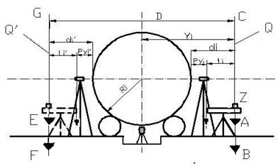
[0009] (1) Next to the high-temperature rotating rotary kiln, it is necessary to manually climb on a support about 5 meters high, and install two horizontal displacement sensors on the horizontal diameter line of the wheel belt to be tested. The operator is safe when working at a height of 5 meters. dangers and difficulties;
[0010] (2) Need to use theodolite and far in X i The surveyor at the office cooperates with the measuring ruler to manually read the horizontal distance reading L of the two displacement sensors to the vertical planes Q and Q' i , L i ’, the operation is complex, tedious and time-consuming, and there are human reading errors, rotary kiln vibration and high temperature and other factors

Method used


Image

  • Detecting and monitoring method and measuring system for dynamic axis and bending of rotary kiln tube
  • Detecting and monitoring method and measuring system for dynamic axis and bending of rotary kiln tube
  • Detecting and monitoring method and measuring system for dynamic axis and bending of rotary kiln tube

Examples


Embodiment Construction

[0039] The present invention is described in detail below with reference to accompanying drawing and specific embodiment:

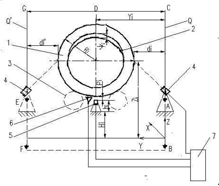
[0040] figure 1 , has been introduced in the background technology, and is omitted here. See image 3 The method of the present invention is as follows: first, a rectangular coordinate system X, Y, Z is established outside the rotary kiln, and the X axis is substantially parallel to the axis of the rotary kiln shell. See figure 2 , and parallel to the X axis, two pairs of targets are fixed at four points A, B, E, and F away from the two sides of the kiln base pier. Based on this, two pairs of targets with a distance of D and parallel to each other are established with a theodolite (A, B, and C are determined ) vertical plane Q and (determination of E, F, G) vertical plane Q′.

[0041] (1) Determine the average abscissa Y i

[0042] At X=X perpendicular to the X axis i Each measuring point X on the ground or other structures where the section in...


PUM


Abstract

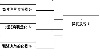
The invention discloses a detecting and monitoring method and a measuring system for a dynamic axis and bending of a rotary kiln tube, wherein the system comprises an instrument for distance measurement and angle measurement, a short-distance measurer, a tube position sensor and a microcomputer system. A coordinate system and two parallel vertical planes are established at both sides of a rotary kiln; at the two vertical planes away from the kiln, the instrument for the distance measurement and the angle measurement can be used for directly measuring horizontal distances from each point on a horizontal diameter line of each kiln body to the two vertical planes, and measuring the height difference from each point on a vertical diameter line of the kiln body to the coordinate system; and the distance measurement accuracy is not greater than + / -1mm. According to the method and the system, the operation of the measurement system is performed on the ground, and the operation is safe and fast, the influence on the measurement caused by factors such as vibration and high temperature of the rotary kiln and artificial reading error can be avoided completely, and the measurement accuracy of a central point and the bending of a rotary kiln tube can be ensured not to be greater than 1.5mm; and the measurement process is obviously simplified and the measurement efficiency is greatly improved.

Description

technical field [0001] The invention relates to a dynamic measurement method for a rotary kiln, in particular to a detection and monitoring method and a measurement system for the dynamic axis and bending of the rotary kiln. Background technique [0002] Rotary kiln is the key firing equipment in the production of cement, metallurgy, chemical industry, refractory materials, etc. The kiln is generally supported by more than three sets of supporting wheels for continuous operation. In the long-term operation, due to the uneven wear of the supporting roller and the tire belt, the thermal deformation of the various parts of the kiln, and the uneven settlement of the kiln base pier, the operating axis of the rotary kiln is not a straight line, which has a periodic deformation effect on the cylinder body . This deformation will affect the transmission mesh of the kiln gear ring and damage the kiln lining and cylinder, resulting in kiln mechanical failure and kiln shutdown acci...

Claims


Application Information

Patent Timeline
IPC IPC(8): G01B21/22
Inventor 张云其他发明人请求不公开姓名
Owner WUHAN UNIV OF TECH
Learn More