Solar selective absorption coating
An absorption coating and selective technology, applied in the field of solar energy, can solve the problems of cumbersome debugging process, achieve the effect of excellent absorption ratio, increase absorption, and simplify debugging procedures
- Summary
- Abstract
- Description
- Claims
- Application Information
AI Technical Summary
Problems solved by technology
Method used
Image

Examples
Embodiment 1
[0041] Embodiment 1: The solar energy selective absorbing coating that the cermet absorbing layer is 4 layers
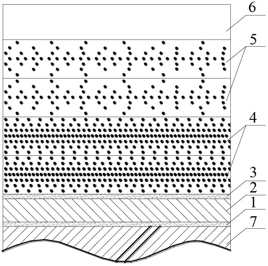
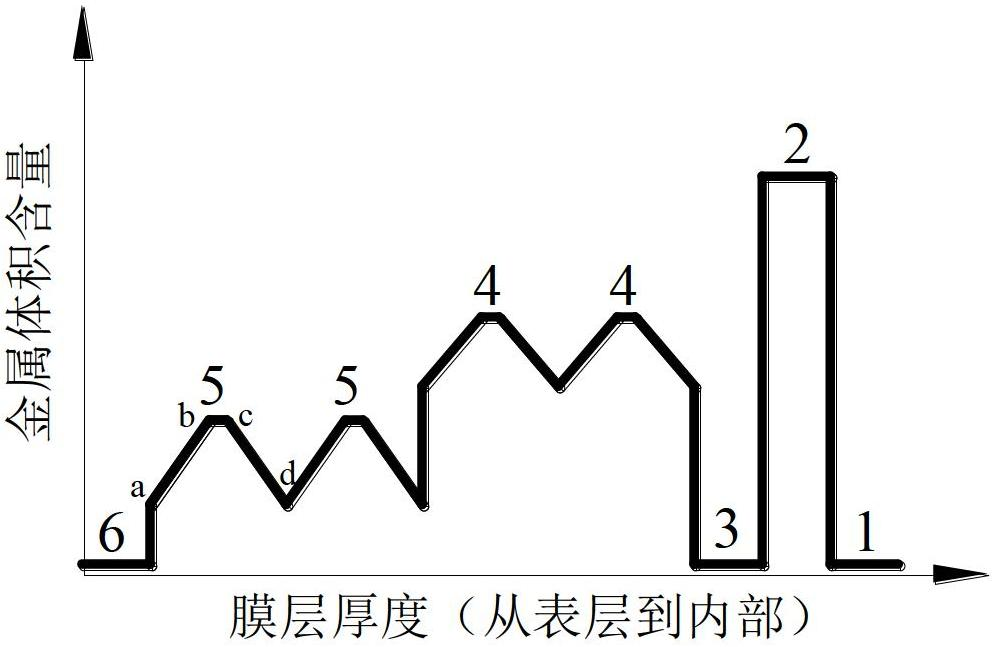
[0042] Deposition of AIN / Cu / AIN / SS-AIN / SS-AIN / AIN solar selective absorber coatings on glass tubes. For specific film structure, see figure 1 Schematic diagram of solar selective absorbing coating structure and figure 2 Schematic diagram of the change of metal volume content from the surface layer to the interior of the solar selective absorbing coating (four absorbing layers).
[0043] Such as figure 1 , figure 2 As shown, a solar selective absorbing coating is composed of a bonding layer, an infrared reflective layer, a diffusion barrier layer, a high cermet absorbing layer, a low cermet absorbing layer and an anti-reflection layer, and the absorbing layer is composed of a cermet The absorption layer is composed of a composite material film composed of ceramics doped with metal particles.
[0044] The anti-reflection layer is made up of transmissive ceramic ...
Embodiment 2
[0059] Embodiment 2: The solar energy selective absorbing coating that the cermet absorbing layer is 2 layers
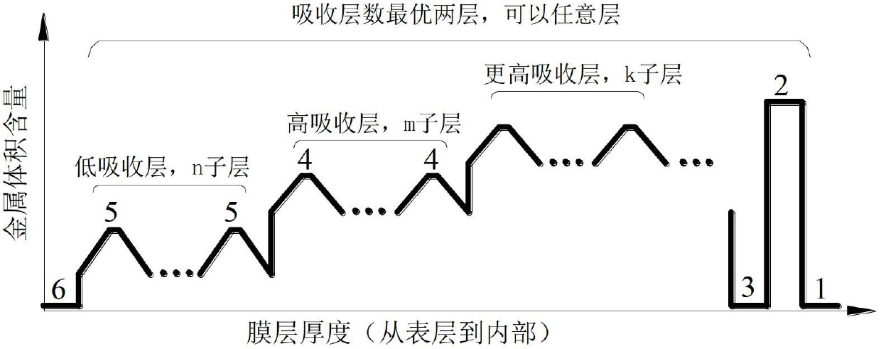
[0060] Deposition of AIN / Cu / AIN / SS-AIN / SS-AIN / AIN solar selective absorber coatings on glass tubes. The coating is basically the same as Example 1, and the specific film structure is shown in image 3 Schematic diagram of the change in metal volume content of the solar selective absorbing coating from the surface layer to the interior. In this example, n is equal to 1, and m is equal to 1, that is, there is only one high cermet absorption layer and one low cermet absorption layer. This example is compared with example 1, only absorbing layer is different, and example 1 has two layers of high cermet absorbing layers, two layers of low cermet absorbing layers, and this example has one layer respectively for high and low metal absorbing layers. The rest of the film structure is exactly the same, and the process parameters are also basically the same. Therefore, this ...
Embodiment 3
[0066] Deposition of AIN / Cu / AIN / SS-AIN / SS-AIN / AIN solar selective absorber coatings on glass tubes. This example is compared with example 1, only absorbing layer is different, and example 1 has two layers of high cermet absorbing layers, two layers of low cermet absorbing layers, and this example has multiple layers respectively for high and low cermet absorbing layers. For specific film structure, see image 3 Schematic diagram of the change in metal volume content of the solar selective absorbing coating from the surface layer to the interior. In this example, n is equal to 24, that is, it contains 24 sublayers of the low cermet absorption layer, and m is equal to 18, that is, it contains 18 sublayers of the high cermet absorption layer. The rest of the film structure is exactly the same as Example 1, and will not be described in detail.
[0067] This example uses a circular coating chamber, the specific structure see Figure 6 Schematic diagram of the distance between th...
PUM
| Property | Measurement | Unit |
|---|---|---|
| Thickness | aaaaa | aaaaa |
| Thickness | aaaaa | aaaaa |
| Thickness | aaaaa | aaaaa |
Abstract
Description
Claims
Application Information
 - R&D
- Intellectual Property
- Life Sciences
- Materials
- Tech Scout
- Unparalleled Data Quality
- Higher Quality Content
- 60% Fewer Hallucinations
Browse by: Latest US Patents, China's latest patents, Technical Efficacy Thesaurus, Application Domain, Technology Topic, Popular Technical Reports.
© 2025 PatSnap. All rights reserved.Legal|Privacy policy|Modern Slavery Act Transparency Statement|Sitemap|About US| Contact US: help@patsnap.com