Assembly for actuating an actuator in a motor vehicle

A technology for actuators and motor vehicles, which is applied to vehicle accessories for anti-theft, vehicle components, excitation or armature current control, etc., and can solve the problem of inability to obtain reliable information on the position of the reaching end.

Active Publication Date: 2012-08-22
HUF HULSBECK & FURST GMBH & CO KG
View PDF5 Cites 1 Cited by
  • Summary
  • Abstract
  • Description
  • Claims
  • Application Information

AI Technical Summary

Problems solved by technology

[0007] Position sensors are generally required to detect all end positions, since otherwise no reliable information about the end positions reached

Method used


Image

  • Assembly for actuating an actuator in a motor vehicle
  • Assembly for actuating an actuator in a motor vehicle

Examples


Embodiment Construction

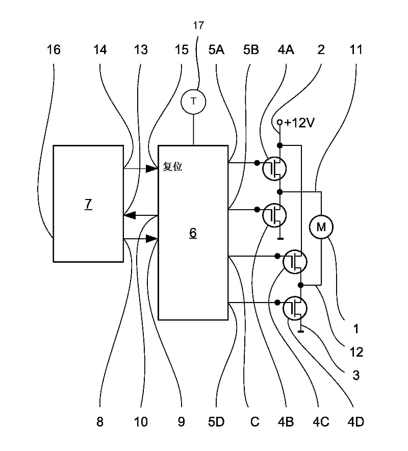
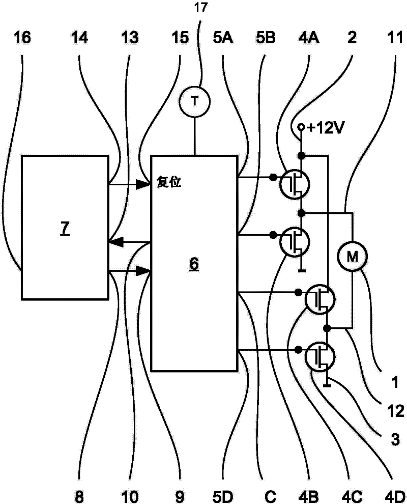
[0028] figure 1 Components of an electronic steering lock (ELV), in particular a motor-driven actuation circuit for the ELV, are shown schematically. A motor 1 , which engages in the steering column by driving the transmission to move the stop pin, is coupled between the supply voltage 2 and ground 3 via power switching means. exist figure 1 In the exemplary embodiment shown schematically, both connections of the motor 1 can be connected either to the supply voltage 2 or to the ground 3, so that the motor can be moved in two directions. An electronic steering lock construction is also known in which the motor always moves in one direction only. In this construct it is possible to cancel figure 1 parts of the power switching device shown in . When the motor 1 should not move, the two terminals of the motor are connected to the ground 3 for safety, that is to say, the power switching device connecting the motor terminals to the ground 3 is caused to remain switched on.

[0...


PUM


Abstract

The invention relates to an assembly for actuating an actuator that can be moved between a first end position and a second end position, comprising a direct-current motor and a gear train for moving the actuator. An end position sensor detects if the actuator is in a second end position, and a control circuit having a PWM motor actuation circuit is actuated for a specified duration in order to move the actuator from the second position to the first position. The assembly comprises a temperature sensor, which outputs a sensor output signal to the control circuit, and the control circuit specifies an actuation duration that depends on the detected temperature.

Description

technical field [0001] The invention relates to an assembly for actuating an actuator in a motor vehicle, the actuator being movable between a first end position and a second end position. [0002] The invention relates in particular to an assembly having in a housing a transmission for moving an actuator, which is driven by a DC motor, wherein the actuator moves in one direction of motor rotation from a first end position to a second two end positions, and moves from the second end position to the first end position in opposite directions of motor rotation; and has an end position sensor that detects whether the actuator is in the second end position . Control circuits with pulse width modulated (PWM) motor control circuits controlled by DC voltage pulses at a frequency greater than 1 kHz at a duty cycle between 100% duty cycle (DC voltage) and a minimum duty cycle A DC motor wherein the control circuit causes the PWM motor control circuit to operate the motor at a predeter...

Claims


Application Information

Patent Timeline
Patent Type & Authority Applications(China)
IPC IPC(8): H02P7/29B60R25/02
CPCH02P7/29
Inventor 弗兰茨-约瑟夫·韦伯
Owner HUF HULSBECK & FURST GMBH & CO KG
Why Eureka
Try Eureka