Electric leakage protection device

A technology of leakage protection device and electromagnetic coil, which is applied in the direction of circuit device, emergency protection circuit device, emergency protection device with automatic disconnection, etc., can solve the problems of leakage protection device and people being electrocuted, and achieve the effect of good electricity safety guarantee

Inactive Publication Date: 2012-08-22
刘睿刚
View PDF7 Cites 1 Cited by
  • Summary
  • Abstract
  • Description
  • Claims
  • Application Information

AI Technical Summary

Problems solved by technology

It can be seen that when in use, when the ground wire of the ground protection system is missing (for example: no ground due to a virtual connection of the ground wire of the socket) and the electrical appliances on the load line of the leakage protection device have leakage due to insulation failure or abnormality of the ground protection system (for example: When the ground wire is accidentally electrified, it will cause dangerous voltage on the shell of Class I electrical appliances, but they have not yet produced residual current or ground fault current, so the existing leakage protection device is in this case. Under normal circumstances, it will not trip automatically. Only when people touch the energized shells, residual current or ground fault current will be generated, so that the leakage protection device will trip within 0.1S, and the phase wire, neutral wire, The ground wire is disconnected. Although it can trip in time to protect people's lives, it can only implement power-off protection after people get an electric shock. Therefore, the existing leakage protection device still has the problem of people getting an electric shock.

Method used


Image

  • Electric leakage protection device
  • Electric leakage protection device
  • Electric leakage protection device

Examples


Embodiment 1

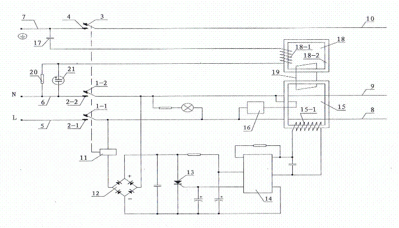
[0025] see figure 1 As shown, a leakage protection device is mainly composed of a shell, a zero-sequence current transformer 15 through which the phase wire 5 at the power supply end, the neutral wire 6 and the ground wire 7, the phase wire 8 and the neutral wire 9 at the load end pass through, and the ground wire at the load end Line 10, test circuit 16, electromagnetic tripping and locking device, first resistance-capacitance element 17, ground fault voltage detector 18, induction ring 19, second resistance-capacitance element 20, neon lamp 21, the electromagnetic tripping The locking device is mainly composed of electromagnetic coil 11 and its driving circuit, phase line contacts 1-1 and 2-1, neutral line contacts 1-2 and 2-2, ground wire contacts 3 and 4, and electromagnetic coil 11 The drive circuit is mainly composed of a rectifier circuit 12, a silicon controlled rectifier 13, and an amplifier circuit 14. The ground fault voltage detector 18 is provided with a detection...

Embodiment 2

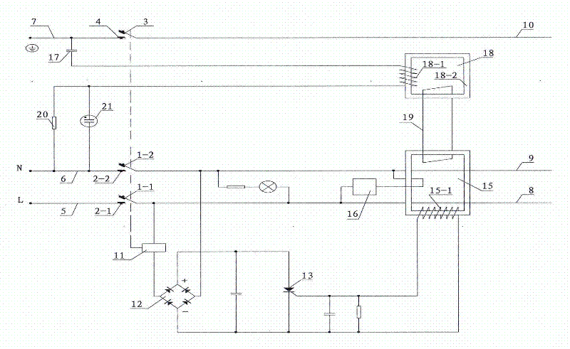
[0038] see figure 2 As shown, compared with Embodiment 1, this embodiment cancels the amplifier circuit 14 in the driving circuit of the electromagnetic coil 11 .

[0039] In this embodiment, the driving circuit of the electromagnetic coil 11 is mainly composed of a rectifier circuit 12 and a thyristor 13. The input end of the driving circuit of the electromagnetic coil 11 is the trigger pole and cathode of the thyristor 13, and the zero-sequence current transformer 15 One output terminal and the other output terminal of the secondary winding 15-1 are respectively connected to the trigger pole and cathode of the thyristor 13, and the anode and cathode of the thyristor 13 are respectively connected to the positive pole (+) and negative pole of the output terminal of the rectifier circuit 12 (-)connect.

[0040] In this embodiment, the induction ring 19 is made of a metal ring, or it can be made of a wire.

[0041] Compared with the first embodiment, only the driving circuit ...


PUM


Abstract

The invention discloses an electric leakage protection device which is not only capable of preventing the accidents of electric shocks caused by faults of electrical appliances but also capable of preventing the accidents of electric shocks caused by accidental electrification of earth wires. The electric leakage protection device is provided with a first resistor-capacitor unit, an earth wire fault voltage detector and an induction ring; a detection coil of the earth wire fault voltage detector is wound on an iron core of the earth wire fault voltage detector; a detection circuit formed by the first resistor-capacitor unit and the detection coil of the earth wire fault voltage detector which are connected in series is connected between an earth wire and a null line; one end of the first resistor-capacitor unit is connected with the earth wire and the other end is connected with one end of the detection coil of the earth wire fault voltage detector; the other end of the detection coil of the earth wire fault voltage detector is connected with the null line; and the detection ring passes through a closed induction circuit formed by the earth wire fault voltage detector and a zero-sequence current transducer.

Description

technical field [0001] The invention relates to the technical field of electricity safety protection, in particular to an electric leakage protection device. Background technique [0002] Chinese patent document CN1142618C discloses a leakage protection plug, which is provided with a zero-sequence current transformer through which both the phase line and the neutral line pass to detect the residual current between the phase and the neutral line, and the ground line There is a ground fault voltage detector to detect the fault current flowing through the ground wire. When the residual current between the phase and neutral wires or the fault current on the ground wire reaches the preset threshold (for example: 10mA), It trips instantly, cutting phase, neutral and ground. It can be seen that when in use, when the ground wire of the ground protection system is missing (for example: no ground due to a virtual connection of the ground wire of the socket) and the electrical applian...

Claims


Application Information

Patent Timeline
Patent Type & Authority Applications(China)
IPC IPC(8): H02H3/32
Inventor 刘睿刚
Owner 刘睿刚
Why Eureka
Try Eureka