
Visual system with real-time parameter monitoring and on-line calibration functions

A vision system and calibration technology, applied in the field of vision systems, can solve the problems of large computing workload of vision systems, affecting the accuracy of visual computing, lack of real-time parameter monitoring and online calibration functions, etc., to achieve the effect of ensuring accuracy

Inactive Publication Date: 2012-08-22
SHANGHAI MARITIME UNIVERSITY
View PDF3 Cites 3 Cited by
  • Summary
  • Abstract
  • Description
  • Claims
  • Application Information

AI Technical Summary

Problems solved by technology

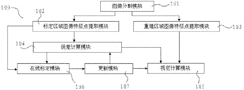
[0005] Aiming at the problems that the existing visual system has a large computational workload and lacks the functions of real-time parameter monitoring and online calibration that affect the accuracy of visual calculation, the present invention provides a visual system with real-time parameter monitoring and online calibration functions. The statistical method is used to obtain the prior probability distribution of the internal parameters of the camera. When the visual system is working under actual conditions, it can monitor and calibrate the internal and external parameters of the camera in real time.

Method used


Image

  • Visual system with real-time parameter monitoring and on-line calibration functions
  • Visual system with real-time parameter monitoring and on-line calibration functions
  • Visual system with real-time parameter monitoring and on-line calibration functions

Examples


Embodiment approach

[0036] Based on above-mentioned principle, an embodiment of the present invention is as follows:

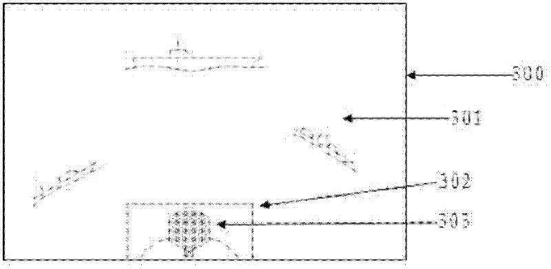
[0037] see image 3 , which is a schematic diagram of images collected by the vision system in an embodiment of the present invention applied to an unmanned surface vehicle.

[0038] In this example, the image 300 collected by the vision system is divided into a monitoring and marking area 302 and a visual reconstruction area 301 . Wherein the monitoring calibration area 302 shows the image 303 of a calibration object whose relative position is fixed relative to the vision system, which is used for real-time monitoring and online calibration of the parameters of the vision system; The part outside the marked area 302 is the imaging area where the visual system observes the surrounding scene, and is used for visual calculation.

[0039] Since the feature points on the calibration object in the vision system are used for both real-time parameter monitoring and online calibration,...


PUM


Abstract

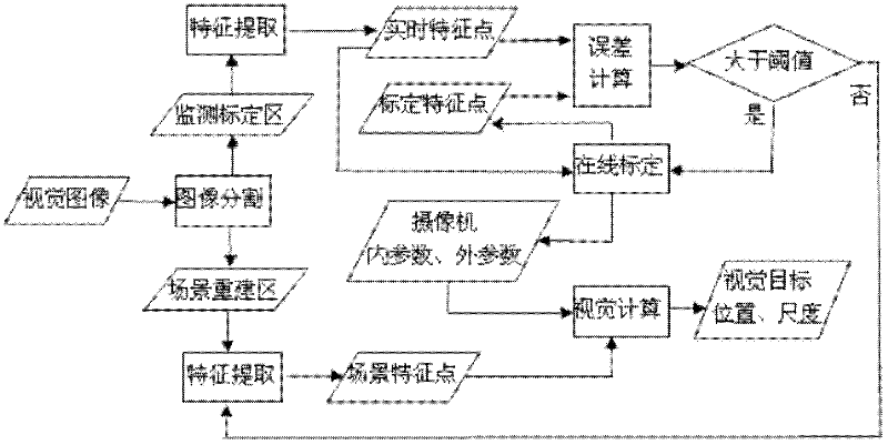
The invention relates to a visual system with real-time parameter monitoring and on-line calibration functions. Collected images are divided into a monitoring calibration region and a visual rebuilding region; the images in the monitoring calibration region are subjected to real-time feature point extraction, and in addition, the extracted feature points are compared with the feature points calibrated in a last time; when the errors of the feature points are smaller than the set threshold, the images in a scene rebuilding region are subjected to feature point extraction, in addition, camera inner and outer parameters calibrated in the last time are used for carrying out visual calculation, and scene information such as visual target position, scale and the like is output; and when the errors of the feature points are greater than or equal to the set threshold, the feature points extracted in real time in the monitoring calibration region are used for calibrating the visual system, the calibrated feature points of the monitoring calibration region and the camera inner and outer parameters are updated according to the calibration results, and the functions of visual calculation, parameter monitoring and on-line calibration are completed. The visual system provided by the invention has the parameter real-time monitoring function and the on-line calibration function, the accuracy of the visual calculation results is ensured, and the system resources are saved.

Description

technical field [0001] The invention relates to a vision system technology, in particular to a vision system with real-time parameter monitoring and online calibration functions, which is suitable for visual navigation or monitoring systems installed on unmanned boats, and can also be used for unmanned vehicles and unmanned aerial vehicle vision systems . Background technique [0002] Visual navigation has been successfully applied in ground unmanned vehicles and aerial unmanned aerial vehicles. In recent years, people have tried to apply this technology to the navigation of surface unmanned boats. The calibration parameters will change due to the turbulence caused by hoisting, deployment or wind and waves; the vision system is affected by the reflection of the water surface, the actual working environment is different from the land calibration environment, and the calibration parameters also have deviations; therefore, people hope to be able to calibrate the vision system ...

Claims


Application Information

Patent Timeline
IPC IPC(8): G06T7/00H04N17/00
Inventor 王建华沈爱弟牛王强高迪驹刘昭周贤文
Owner SHANGHAI MARITIME UNIVERSITY
Learn More